
Secret High Power Free Energy Circuit (AEC)
")
Those coils consist of two aluminum foils taken from a large electrolytic capacitor, wound on the ferrite core with a dielectric insulator in between, specifically plastic film. Each coil/capacitor has 60 turns of foil pairs, with an inductance of approximately 0.53mH and a forming capacitance of 48μF for each finished coil. Each coil/capacitor has four terminal ends, two at the start and two at the end. The circuit employs three of these coils for output, and they should be made as identical as possible. Capacitors may need to be adjusted based on the forming capacitance and inductance of the coils. The circuit includes two variable capacitors and a variable resistor to tune the circuit for resonance.
A proper earth connection is essential and must be completely separate from the house mains earth. It is recommended to start with low power, applying 3 volts to the joule thief and gradually increasing the voltage with the load connected. First, adjust the variable resistor for optimal output, then tune the variable capacitors to match the frequencies. Caution is advised while working with this unit, as it can produce high voltages that may cause severe injury or be fatal if not handled properly.
The Tesla/joule thief hybrid circuit is an innovative design that combines the principles of energy harvesting and amplification. The use of the 2N3055 transistor allows for efficient switching and amplification of the input signal, while the bifilar coil configuration ensures that the magnetic field produced is maximized. The incorporation of capacitor/coils also enhances the circuit's performance by allowing for energy storage and release, providing a more stable output.
The ferrite core plays a crucial role in the circuit's operation, as it enhances the inductance and allows for better energy transfer. The careful winding of the aluminum foils into coils ensures that the inductance and capacitance are optimized, creating a resonant circuit that can produce high-frequency outputs. The tuning components, including the variable resistors and capacitors, allow for precise adjustments to the circuit's resonance frequency, which is critical for achieving maximum efficiency and power output.
Safety precautions are paramount when working with high-voltage circuits. It is essential to ensure that all connections are secure and that the circuit is properly grounded. An isolated ground connection separate from the mains is crucial to prevent electrical shock. Additionally, testing should begin at low voltages to verify circuit functionality before gradually increasing to higher levels. Proper knowledge of high-voltage systems is required to mitigate risks associated with experimentation.This is a Tesla/joule thief hybrid circuit that its inventor claim to produce 90 times the input power! The circuit can be self looped and can provide 1050W of power. from the 1050W only the 11.6W will loop back to supply the joule thief. If you remove the bridge rectifier and the C capacitor you can use the circuit with high frequency AC output.
The circuit uses the 2n3055 and a regular bifilar coil "BC" (45+45 turns, 0.5mm wire) to pulse the ferrite core which consist of two large U shape ferrites. The Coils CC1, CC2 and CC3 are not ordinary coils, Are Capacitor/coils combination.
Those coils are no more than two aluminum foils taken from the guts of a large electrolitic capacitor and winded on the ferrite core with a dielectric insulator between them, Plastic film in that case. Each Coil/capacitor has 60 turns of foil pairs. Inductunce should be around 0.53mH and the forming capacitance 48μF for each finished coil.
So each coil/capacitor has four terminal ends and not two as a regular capacitor has.
Two at start and two at the end. The circuit use three of these coils for the output. Try to make them as identical as they can be. Capacitors may need to be changed according to the forming capacitance and inductunce of your coils. The two variable capacitors and the variable resistor are needed to tune the circuit to resonate.
The earth connection must be good and must be completely seperate from the house mains earth. Start with low power, put 3 volts at the joule thief and gradualy increase the voltage with the load connected.
Tune first the variable resistor for best output, and then tune the variable capacitors to match the frequencies.
Be very carefull while you playing with this unit. You should be expert in high voltage if you decide to experiment with this circuit. If tuned properly, its output can shock you very badly or even kill you.
Related Circuits
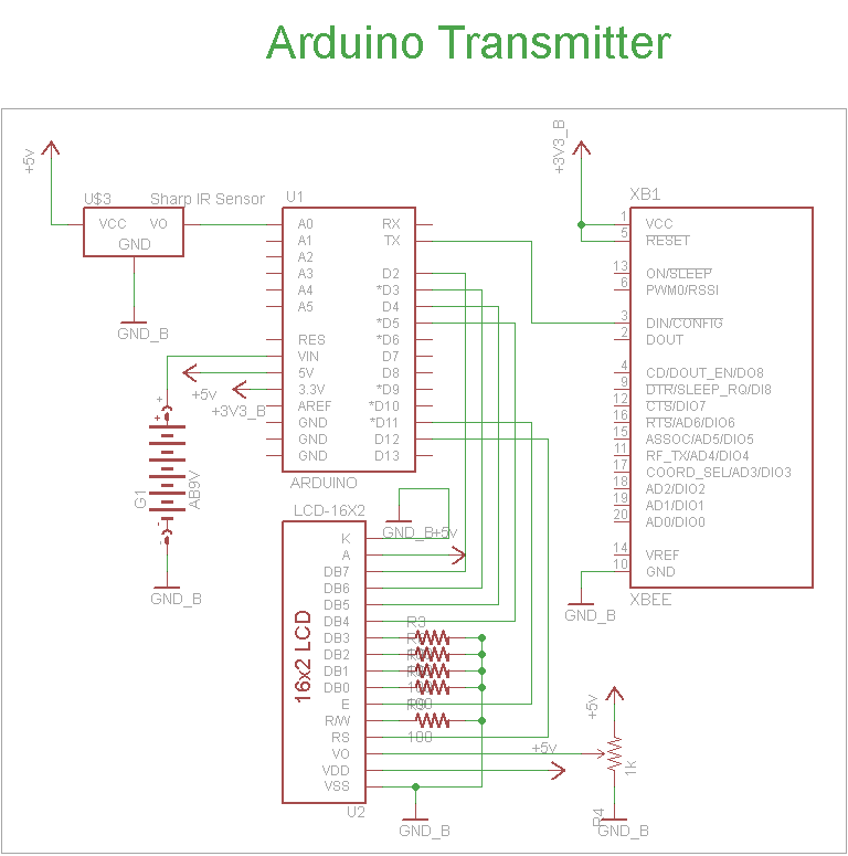
The schematic for the transmitter in this project consists of four main components: the Arduino UNO, the Sharp IR distance sensor, the XBee wireless modules, and a 16x2 LCD. The connections between these components are illustrated in the schematic....
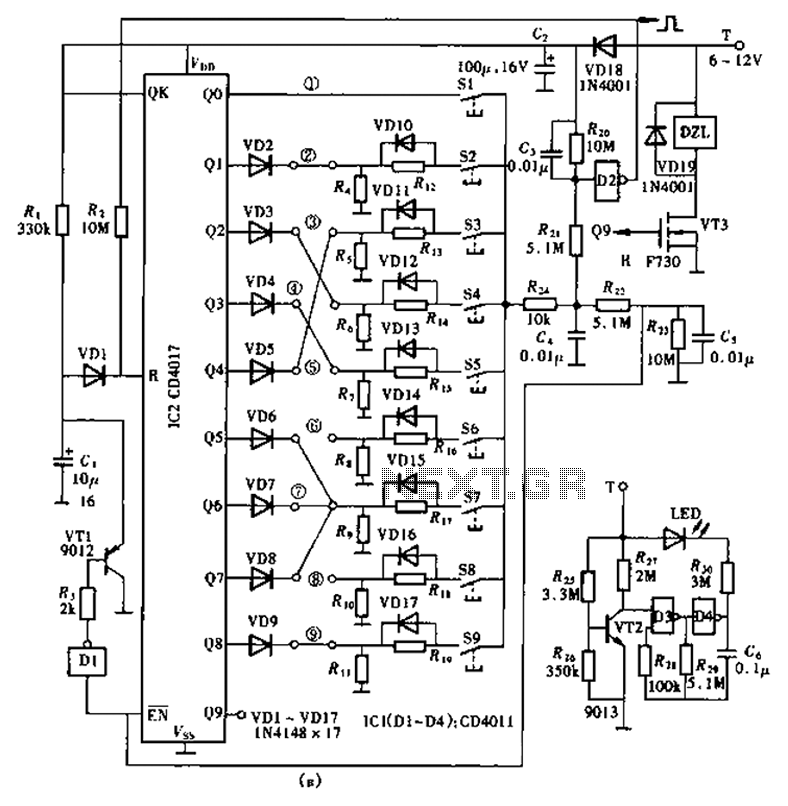
The lock circuit utilizes a decimal counter CD4017, which consists of ten output terminals. These terminals are connected through a combination that corresponds to a group of passwords, allowing for a maximum of up to 100 million combinations, hence...
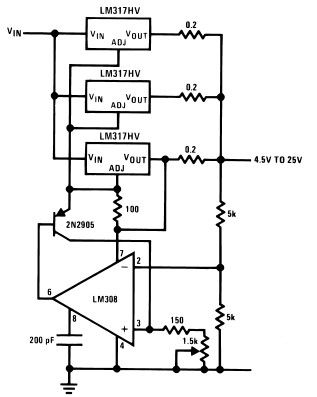
The LM317HV adjustable regulator is capable of supplying over 1.5A across an output voltage range of 1.2V to 57V. The design of this high current power supply is straightforward, as the LM317HV requires only a few external resistors to...
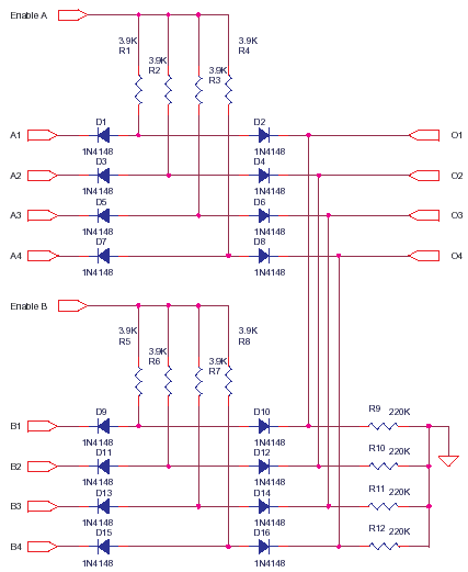
This circuit represents a low-cost printer sharing device that was developed some time ago. The product was encapsulated in epoxy with a black dye and had a limited commercial release. The output impedance of this circuit is high, with...
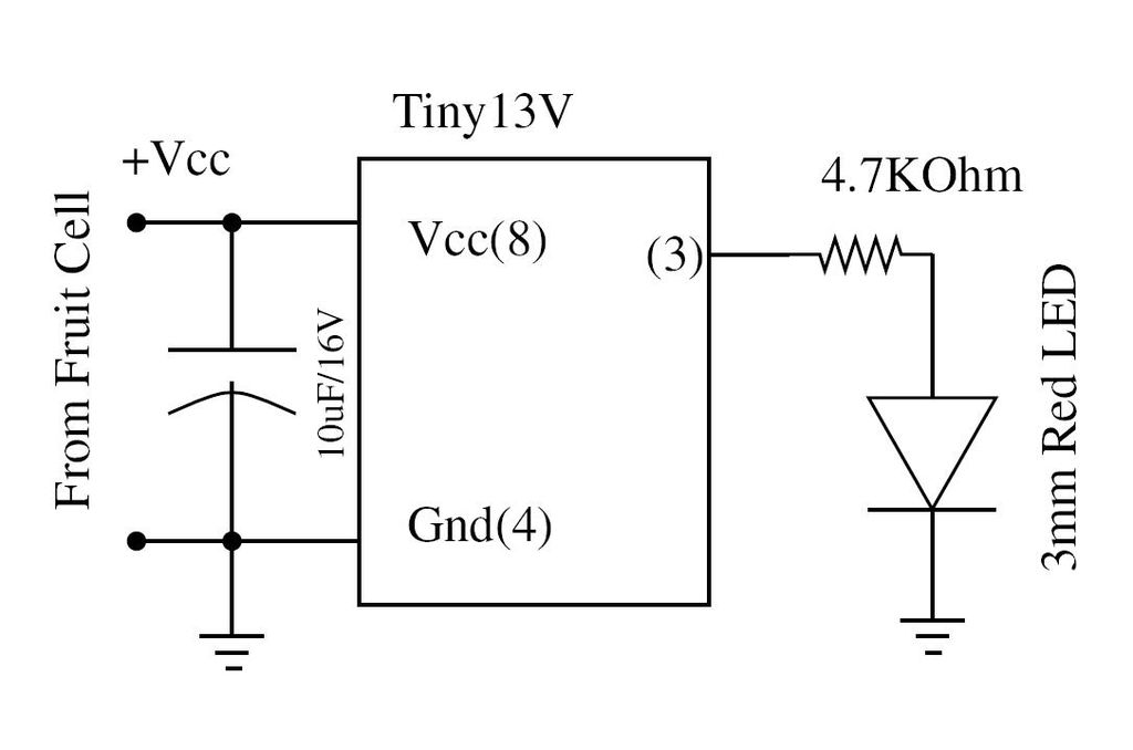
Wire the circuit diagram shown here on a breadboard. The choice of V type of AVR is important. For example, Tiny13V is very appropriate for such an application. To successfully implement the circuit diagram on a breadboard, several considerations must...
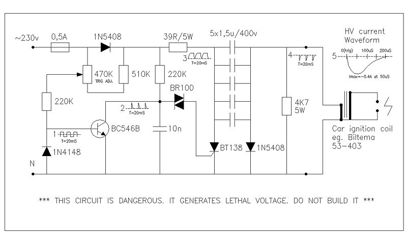
This circuit generates high voltage pulses from a 230 VAC line voltage. The drive end's swing comparator circuit was developed by the creator of this page. The working end is derived from a stroboscope trigger supply circuit. All circuits...