
Combination Voltage And Current Regulator Circuit
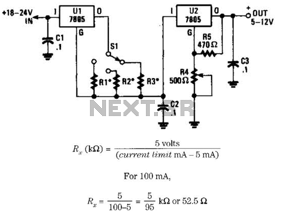
This circuit utilizes two 7805 voltage regulators to create a voltage regulation and current limiting system. The 7805 is a popular linear voltage regulator that outputs a stable 5V, making it suitable for various electronic applications. In this configuration, the two regulators work together to provide both voltage regulation and the ability to limit the current flowing through the circuit.
The resistors R1, R2, and R3 play a crucial role in setting the current limit. The selection of these resistors must ensure that when the maximum current is drawn, the voltage drop across them is precisely 5V. The values of these resistors can be calculated based on Ohm's Law, taking into consideration the maximum allowable current for the specific application. The switch S1 allows the user to select between three different current limits, providing flexibility in the operation of the circuit.
It is essential to account for the current consumption of the voltage regulator itself. In this case, the regulator U1 requires a minimum of 5 mA to function correctly. Consequently, the design must ensure that the minimum current limit setting is at least 10 mA or higher to maintain proper operation. This requirement is satisfied by using a resistor value of R1 equal to 1.25 kΩ, which can be adjusted based on the desired current limits.
The overall design should include proper heatsinking for the 7805 regulators, as they may dissipate significant power when operating near their maximum current limits. Additionally, bypass capacitors should be placed close to the input and output terminals of the regulators to ensure stable operation and reduce noise in the output voltage.
In summary, this circuit provides a reliable solution for applications requiring both voltage regulation at 5V and the capability to limit current to protect downstream components from excessive current flow. Proper selection of resistors and consideration of the regulator's operational requirements are critical to achieving optimal performance. This voltage-regulator/cuiTent-liimter combination can be made from two 7805 regulators as shown. Rl, R2, and R3 shouldbe selected for a 5-V drop at the maximum allowable currant limit. SI selects one of the three current values. Do not forget that Ul requires 5 mA to operate and this means that the minimum current limit setting should be 10 mA or more (Rl - 1.25 kQ). Resistor values are as shown. 🔗 External reference
Related Circuits
In a panic situation during the night when an intruder attempts to break into a house, this alarm system will assist by emitting a loud police siren to deter the intruder. The alarm system is designed to enhance home security...
The CD4538 is a dual Monostable Multivibrator. When triggered, the chip generates a single pulse or a high-low event. The T+ pin (pin 4) of U1a serves as the positive edge trigger input, while the T- pin (pin 5)...
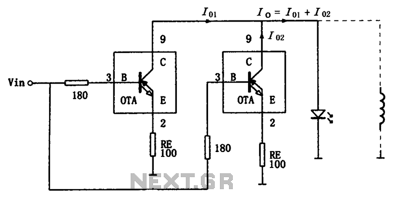
The high-speed parallel current drive circuit utilizes the OPA660 operational transconductance amplifier (OTA). An input signal, Vin, is connected to a 180-ohm resistor equivalent device at the base (pin 3) of the OPA660. The collector (pin 8) is directly...
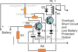
The battery voltage must pass through resistor R1 before reaching the output load. As a result, the current flowing through R1 is proportionately transformed into a voltage across it. When the battery voltage drops below a certain threshold, the...
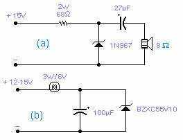
These two circuits are interesting from an academic point of view. Their practical implementation is rather critical and it is not easy to get steady operation. Circuit (a) requires a "cooked" zener: connect it first to a constant current...
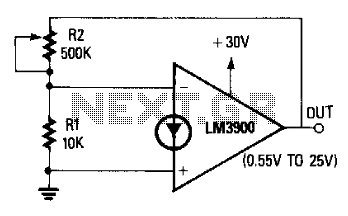
The non-inverting terminal of the operational amplifier (op-amp) is grounded, and the circuit utilizes the voltage at the inverting terminal as a reference. The voltage gain of the circuit is determined by the ratio of resistors R2 to R....