
Problem With Electrical Distribution
An effective troubleshooting approach for the described electrical issue involves a systematic examination of the boat's electrical distribution system. Begin by confirming the integrity of the power supply from the battery to the GPS unit. Using a multimeter, measure the voltage at the battery terminals to ensure it is supplying approximately 12.8 volts. Subsequently, check the voltage at the GPS unit's power connector. If the voltage drops below the expected level at any point along the circuit, it indicates a potential fault in the wiring or connections.
To facilitate the troubleshooting process, sketch a wiring diagram that outlines the connections from the battery to the GPS unit. Label each connection point, allowing for easy reference during testing. As voltage measurements are taken, document the readings at each connection point sequentially. If a drop in voltage is detected, inspect that segment of the wiring for damage, corrosion, or loose connections.
In addition to checking the wiring, it is essential to examine the fuse box for any blown fuses or poor connections that could interrupt the circuit. Marine environments can accelerate the degradation of low-quality wiring, leading to insulation breakdown and increased resistance. It may be prudent to replace existing lamp cord with high-quality marine-grade wire, which is designed to withstand harsh conditions and reduce the likelihood of future electrical issues.
When rerouting or replacing wiring, consider using protective measures such as zip ties or conduit to prevent abrasion against sharp edges and to minimize noise caused by movement within the mast. By implementing these strategies, the reliability of the electrical system on the sailboat can be significantly improved, reducing the risk of similar issues arising in the future.I own a 2005 McGregor 26 sailboat. I had a Standard Horizon CP150C installed in my boat. I recently moved my boat to British Columbia, Canada and to my surprise my GPS unit did not power on. Although it is an old model it is brand new. I am the original owner and never had the opportunity to use in the lakes I sailed in the Prairies. I took the GP S and chart plotter for inspection with a Standard Horizon licensed service shop in Vancouver, who checked the unit and found no problems with it. I took it back to my boat and it still did not power on. This clearly indicates that there is a wiring problem. Because my boat is presently docked in a remote place I cannot get an electrician to check my wiring.
So I have to find a solution on my own. I opened the side of the cockpit to check the wiring to the GPS plug and [the wiring] looks OK. I went all the way to the battery connections and they also look OK. I visually checked the fuse box connections and also look OK. I am by now completely puzzled about what could be the source of the problem. Any suggestions and ideas to help solve this problem are greatly appreciated. While making a careful visual inspection of electrical circuits is a good way to locate problems which have occurred when there is a clear physical manifestation of the problem, a visual inspection cannot always detect a bad connection. To test an electrical distribution circuit, begin by testing for voltage at the source of the voltage.
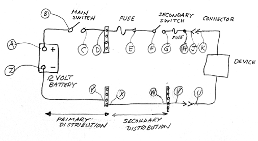
Move along the distribution circuit with your test voltmeter, checking for voltage at each point in the electrical distribution where there is any sort of connection from the source. You should be able to easily located a bad connection in this manner. One can often find a problem by drawing/sketching a wiring diagram of the wiring - as built. This sketch doesn`t have to be fancy - or to scale, just showing the wires and the components in the circuits.
With a sketch, the problem often just kinda "leaps" out at you. Here is a sample of a sketch of electrical distribution on a small boat from the battery to a device. I have added callouts along the circuit in order to make it possible to refer to various points in the circuit: Now, disconnect the test meter positive lead from A and connect to B.
You should again measure the same voltage, 12. 8-volts approximately. Proceed to test all points shown in the positive distribution, moving your test meter positive lead in sequence from A to B to C and so on, on to K. If at any point you fail to measure the battery voltage, you can investigate the circuit more closely for a discontinuity in the circuit that would interrupt current flow.
Confirm the voltmeter still shows 12. 8-volts (approximately). Now move the negative lead of the test meter to points Y, X, W, V and U, again checking to see that the voltmeter shows the proper reading. If find any point where the voltmeter reading changes, carefully inspect that portion of the circuit for any discontinuity.
I just ran into this thread today and would like to make a couple comments and observations. In addition to a Whaler, I [also] have a [1996 Macgregor 26X sailboat, the] same as [the originator of this discussion]. Unlike a Whaler, these are inexpensively built vessels, and need to be modified by the owner to suit their intended use.
I rigged mine to run open ocean and island hop, which it did well for many years. I`m assuming by now [the originator of this discussion has] found the electrical problem and fixed it. The advice of Jim and Jerry probably got you there with ease. Here`s my observation about Macgregor wiring: They use dime-store lamp cord. This wire will begin degrading immediately in a marine environment, and if not changed to quality wire, electrical problems will continue to plague the vessel.
When you have a bit of time and a good working environment, consider changing out all the remaining lamp cord. Some of the runs are testy, so the best course is to solder new wire to the old and pull it thru. At anchor in an unsettled bay, the mast draws an arc in the sky and the wire inside slaps against the mast, whose noise radiates down inside the cabin.
Very annoying. After re-wiring the mast, the wiring bundle was wrapped with four zip ties each at 3` intervals. Kind of hard to explain, but zip tie ends (untrimmed) sticking out deny the wire from ever touching the mast. It`s a standoff spring I guess. Some sailors have taken to running wire thru rubber balls every few feet, but the thought of water soaked balls on the inside of an aluminum mast scares me.
We have no idea if Emilio, the originator of this discussion, has resolved his electrical problems, or if he has even read a word of the advice offered. He has never returned to the discussion he started to acknowledge any of the follow-on articles. Thanks for the comments on how to rig a wire in a tall hollow mast to reduce the slapping noise. If Boston Whaler boats had tall masts, they`d probably be filled with foam to improve their floatation characteristics.
My experience with low-quality insulated wire is the vinyl insulation often contaminates the copper wire, resulting in a conductor that is difficult to crimp or solder. With quality marine grade wire like ANCOR now widely available and at decent prices, it makes no sense to use hardware store zip cord made in China.
Emillio, Emillio where art thou Right Jim, he probably changed channels and will be gone until the next glitch. I haven`t been hanging around these parts all that long, but have seen a few quick in/out threads come across the screen.
Not a bad thing I suppose. Folks in the boating world have found they can get cogent answers to tough questions here, Whaler or not. Good work on maintaining the high level of conversation. 🔗 External reference
Related Circuits

The circuit consists of two separate 3023 optoisolators controlling two distinct triacs, each responsible for powering a large 3-phase contactor. One contactor operates correctly, while the other experiences issues, not receiving sufficient power to engage fully. The upper image...

The microphone issue on the Nokia 6630 is typically attributed to several factors, including a damaged microphone, a broken circuit path, or a faulty UEM IC. If the issue arises from a broken path in the microphone circuit, it...

Numerous effective In-System Programming (ISP) designs are available for 8-bit AVR microcontrollers. However, many of these designs necessitate a pre-programmed microcontroller, presenting the "Chicken or Egg" dilemma: programming microcontrollers requires having one that is already programmed. While solutions utilizing...

The agriculture and electrical power harrow plow power cord must consist of four rubber cables, with one core wire designated as the ground wire. The traction machine housing must be properly grounded. The two traction power machines are connected...
Construct a Wien bridge oscillator that operates at 2.1 kHz and can be activated by a transistor. The inclusion of a transistor switch in the circuit allows for control of the oscillator's operation from a PIC microcontroller. However, during...

The electrical equipment overload and phase failure protection circuitry includes a +12V and +5V DC power supply, an AC transformer, voltage comparators, timers for blockade, a relay control circuit, and a phase loss protection circuit. The DC power supply...