
PTT Schematic
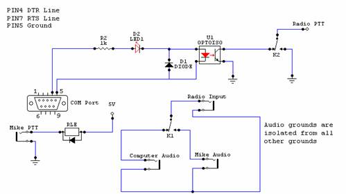
The described circuit for interfacing a computer with a transceiver employs an optocoupler to achieve electrical isolation and reduce component count. The connection utilizes a standard serial COM port, specifically leveraging the RTS or DTR lines to control the PTT function of the transmitter. The optocoupler, designated as U1, plays a critical role in isolating the computer's circuitry from the transceiver, protecting both devices from potential electrical interference or damage.
The circuit design begins with the COM port output, where the RTS line is used to signal the transceiver. When the software activates this line, it transitions from a negative voltage state to a positive voltage state. This change triggers the optocoupler, allowing current to flow from its emitter to collector. The incorporation of LED D1 provides a visual feedback mechanism, indicating the operational status of the interface. In its upgraded form, the dual-polarity LED enhances usability by providing clear visual cues for both RX and TX states.
Analog audio signals from the computer's sound card are routed directly to the transceiver's audio input, ensuring a straightforward connection that minimizes additional components. The design prioritizes simplicity and cost-effectiveness, making it an ideal solution for amateur radio operators seeking an affordable method to integrate their computers with existing transceiver technology. Overall, this circuit exemplifies an efficient and practical approach to enhancing communication capabilities in amateur radio setups.Most modern transceivers have a built in interface. These interfaces work well in digital modes, but seem to lack support in analog voice modes. A case in point is the Yaesu transceivers that only permit the use of their internal interface when the transmitters are set to Digital Mode . Commercial external interfaces cost 100 Euro or more, depending on the additional futures. Due to the fact that most ham operators are on a limited budget, a homebrew approach is attractive. After examining various ways to interface the transceiver, it was found that the most practical way was using an Optocoupler via a COM port. The gain of using an Optocoupler in this project is obvious. First of all, the total number of components is reduced, and the electric isolation between the transceiver and the computer is achieved.
Last but not least, the total cost of the interface is less than 5 Euro -quite a difference compared to the prices of the commercial interfaces available. The voltage swing on these lines is -12v/-5v through +12v/+5v, so a Optocoupler can handle quite nicely the negotiation between the rig and the computer.
The interface is needed so the computer can send a request to the transmitter to transmit or receive. The most practical method is via a serial COM port using the RTS or DTR lines. Through these lines the PTT (Push to Talk) on the transmitter is activated. The analog audio is passed from the sound card directly to the audio in of the transceiver by simple cable connection.
The circuit described below was made to connect the computer to the transmitter. It was designed as simple as possible to keep the number of components as low as possible. As soon as the program activates the RTS line (or the DTR) the negative voltage of the line turns to positive. This makes the Led D1 as well as the Led in the Optocoupler U1 to light, making the emitter and the collector of the Optocoupler to conduct, thus giving the ground needed to the transmitter to TX.
The Led D1 is not necessary for the circuit to work but it is a very useful visual indication of the status of the interface. An upgrade to this simple interface was to replace the Led with a dual polarity Led. This way, instead of having the led light up on TX, the led is green on Stand by (RX) and turns Red on TX.
🔗 External reference
Related Circuits
L2 RFC (resistance 1MOhm with an inductor wrapped around it, composed of multiple coils made from fine insulated wire. The scratch of the inductor connects to the resistance, forming a parallel L-R circuit.) With capacitors C7 and C8, we...
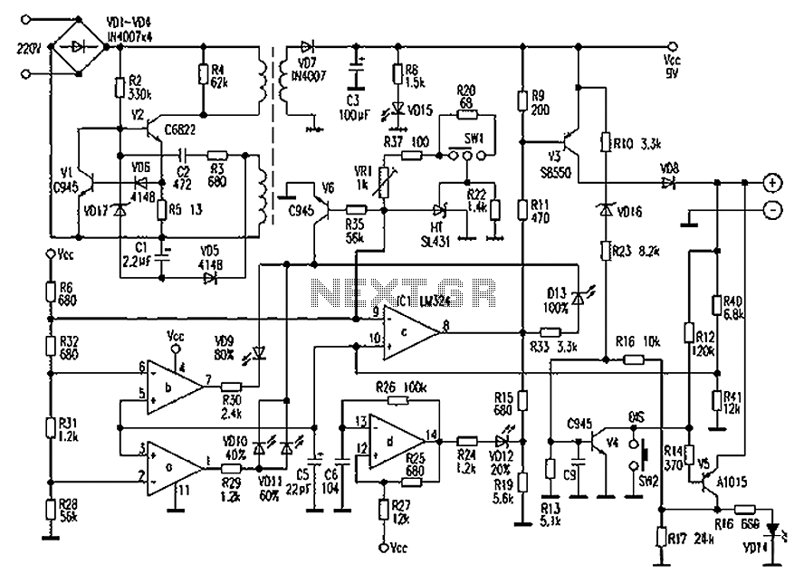
The circuit below responds to sound pressure levels from about 60 to 70 dB. The sound is picked up by an 8 ohm speaker, amplified by a transistor stage and one LM324 op-amp section. You can also use a...
Chaolitong Phone Travel Charger for Motorola models 308, 328, 338, and 368 series mobile phone batteries. This charger features a switch for nickel-cadmium, nickel-hydrogen, and lithium-ion batteries, along with a discharge function. It operates with an AC mains input...
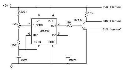
This circuit enables the testing of a servo motor. The angle of the servo can be adjusted using a 10k potentiometer. It is possible that not all positions can be achieved with this circuit; experimenting with different resistors may...
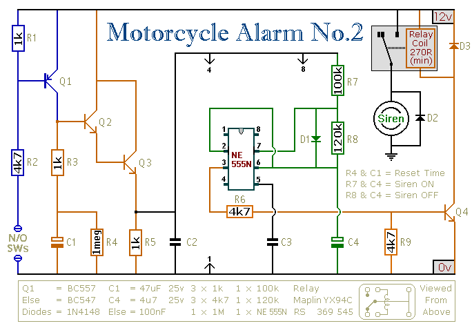
This circuit features an intermittent siren output and automatic reset. It can be operated manually using a key-switch or a hidden switch; but it can also be wired to set itself automatically when you turn-off the ignition. By adding...

The circuit is designed to charge 2.4V, 4.8V, and 9.6V NiCd batteries. The LM317T integrated circuit (IC) shown in this NiCd battery charger schematic is utilized to regulate the voltage for charging the NiCd batteries. The LM317T IC has...