
Sweep/Function Generator


The MAX038 function generator chip is a versatile device designed for generating waveforms with high precision and low distortion. It operates across a frequency range that exceeds 20 MHz, making it suitable for various applications in electronics testing and signal generation. The chip can produce sine, square, and triangle waveforms, with the amplitude being adjustable and output impedance kept low, which is advantageous for interfacing with other circuit elements.
The design incorporates a frequency marker circuit, which is crucial for setting and identifying specific frequencies during operation. The implementation of two selectable controls allows users to fine-tune the output frequency. The variable symmetry of the waveform, particularly for square wave outputs, enhances the usability of the generator for different applications, such as modulation and signal processing.
To facilitate frequency sweeping, the generator is equipped with a FLOW and FHIGH control mechanism. By pressing the FLOW button, the user can set the lower limit of the frequency sweep, while the FHIGH button sets the upper limit. The SWEEP button initiates the sweeping action, enabling the output signal to transition smoothly from the FLOW frequency to the FHIGH frequency and back. This feature is particularly useful in applications requiring frequency modulation or in testing scenarios where a range of frequencies must be explored.
The circuit design heavily relies on multiplexers to manage the selection of frequency set pots, which include the Low Frequency Set Pot, High Frequency Set Pot, and Marker Set Pots. This multiplexing capability allows for seamless transitions between different frequency settings, ensuring that the output frequency can be accurately monitored and adjusted. The output can be interfaced with external measurement tools, such as frequency meters and oscilloscopes, providing comprehensive feedback on the generator's performance.
The MAX038's oscillation frequency is controlled by a voltage that is generated by a sawtooth waveform or a DC voltage derived from the frequency setting pots. The circuit includes resistors R19 and R20, which convert a -3V to +3V control voltage into a control current for the voltage-controlled oscillator (VCO). This conversion is essential for maintaining a linear relationship between the control voltage and the oscillation frequency, thereby enhancing the precision of the output signal.
Capacitance considerations are also critical in the design. The band switch leads exhibit capacitance that can affect the oscillator's performance. To mitigate this, a capacitor is strategically placed on the circuit board next to the MAX038, which helps to stabilize the oscillation frequency at around 21 MHz, even though the chip can theoretically operate at higher frequencies under optimal conditions.
For waveform selection, control inputs A0 and A1 can be managed by a microcontroller or through mechanical switches. This flexibility in control allows for integration into various user interfaces, accommodating different operational preferences. The design can function effectively without a microcontroller, using electromechanical switches instead, which may be preferable in certain applications.
Overall, the MAX038 function generator circuit represents an advanced solution for generating precise waveforms across a wide frequency range, making it a valuable tool in electronic design and testing environments.Maxim's MAX038 function generator chip is capable of producing nearly constant amplitude sine, square, and triangle waves with a low output impedance, from a very low frequency to more than 20 MHz. Basically, a function generator on a chip. Here is a function/sweep generator that uses the MAX038 chip. The design described on these pages are not so much instructions for duplicating the design as they are a collection of ideas to stimulate your own thoughts.
The symmetry of the waveform, or duty cycle in the case of the square wave output, is variable. The performance of the generator is highly dependent upon physical layout. There is one frequency marker circuit and two selectable controls. This, in conjunction with the ability to switch the oscillator's frequency control to the selected marker pot allows accurate setting or location of the frequency marker. To set up the generator to sweep a given frequency range, first select the band that covers the frequency of interest. Press the FLOW button and then adjust the FLOW pot to set the lowest frequency in the sweep range, for example 400 kHz.
Then press the FHIGH button and adjust the FHIGH pot to the highest frequency in the sweep range, for example. 500 kHz. Then press the SWEEP button and the output signal will repetitively sweep from frequency set with the FLOW up to the frequency set with FHIGH pot, in this case, from 400 kHz to 500 kHz, then the frequency will rapidly return to the FLOW.
The large envelope in the middle of the waveform in the photograph above shows the bandpass of a 455 kHz ceramic filter, The two smaller envelopes at the sides correspond to when the generator rapidly sweeps through that frequency again as it returns the MAX038 to FLOW in preparation for another sweep. FLOW must be set to a frequency lower than that to which FHIGH is set in order for the circuit to sweep.
The Much of the circuitry is dedicated to controlling the voltage that controls the MAX038's oscillation frequency. Multiplexers allow the selection of the Low Frequency Set Pot, High Frequency Set Pot, either of the two Marker Set Pots, or when the inputs to the multiplexer are properly set, the circuit toggles between the Low Frequency Pot and High Frequency Set Pot as the MAX038 output frequency is swept between the corresponding frequencies.
Since the output of the MAX038 can be set to correspond to the setting of any of these four pots, enabling the measurement of the sweep start and stop frequencies, and the frequency of either marker with an external frequency meter or oscilloscope. Use the MAX038 data sheet as reference. The things to note on this schematic is that there is an switch to switch the symmetry control between variable and the chip's fixed symmetry setting, and that R19 and R20 convert a -3V to +3V control voltage an the VCO control current.
Thus, the oscillation frequency is a pretty linear function of control voltage. The frequency control voltage is supplied by the saw tooth generator circuit, the output of which will be either a DC voltage from one of the four frequency setting pots (F Low, F High, Marker 1, Marker 2) or a saw tooth waveform. The capacitance on the leads to the band switch, is pretty large compared to the oscillator capacitance, 10 to 15 pf in my case, so I did not put a capacitor on the band switch, but selected a capacitor to go on the circuit board next to the MAX038.
The MAX038 that I used can oscillate up to 30 MHz when the weather is right, but the output of the chip starts to drop and the square and triangle waves both look like sine waves above 20 MHz anyway, so I selected a capacitor that limits oscillation frequency to about 21 MHz. The two waveform select control inputs, A0 and A1 are driven by microcontroller PORTD, bits 2 and 3 respectively.
Alternatively, you can control these inputs with two pole rotary switch set up to encode A0 and A1 according to the data sheet, or use a pair of SPST switches and a pair of pull-up resistors, or use a pair of pull-down resistors and use an ON-OFF-ON toggle switch to select the Sine, Square, or Triangle waveform. A microcontroller is the interface between the buttons on the front panel and the circuitry controlled by them.
There is no need to use a microcontroller as all the circuits can be controlled by electromechanical switches -I just used a controller because I prefer buttons to other kinds of switches. 🔗 External reference
Related Circuits
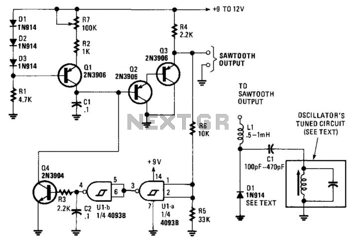
This circuit generates a linear sawtooth waveform with a frequency range from 30 Hz to 3,000 Hz. Q1 acts as a constant-current source that charges capacitor C1 until the output level at the emitter of Q3 triggers operational amplifiers...
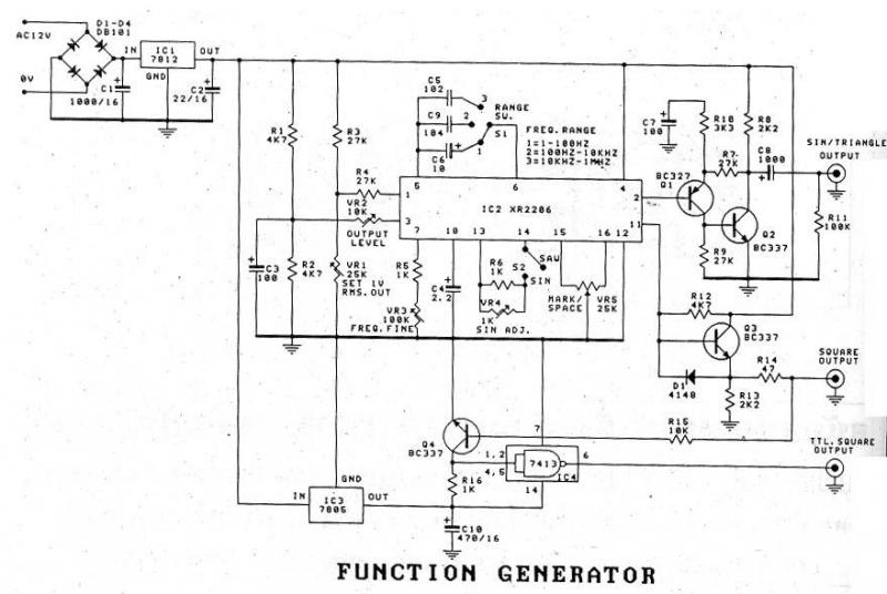
The XR2206 Function Generator is a versatile waveform generator capable of producing sine, triangle, and square waveforms. It operates within a frequency range of 1 Hz to 1 MHz, with frequency adjustments facilitated by variable resistor VR3. The output...
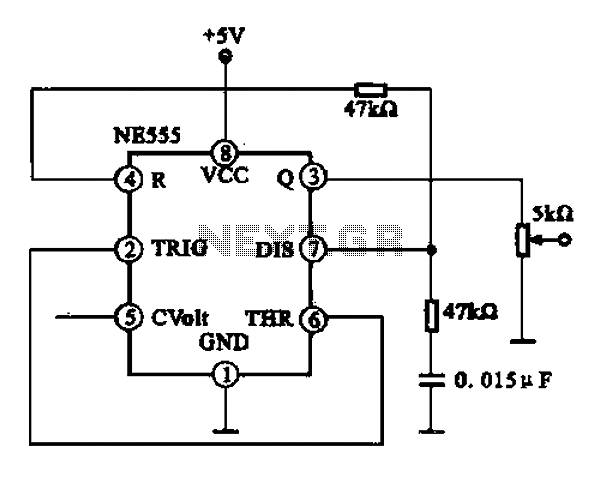
A 1 kHz square wave signal generator is created using a time base circuit with an NE555 timer, combined with a time constant circuit consisting of a 47 kΩ resistor and a 0.15 µF capacitor. The circuit utilizes the...
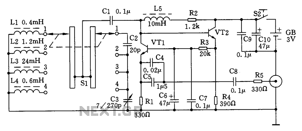
This is a simple high-frequency signal generator. By changing the inductance of the LC resonant circuit using the band switch S1, the high-frequency oscillation frequency range can be altered. The generator is divided into four frequency stages: the first...
A mechanical power source is required, such as a turbine powered by falling water, a wind turbine, a gas turbine, or a steam turbine. A shaft from one of these devices is connected to a generator to produce power....
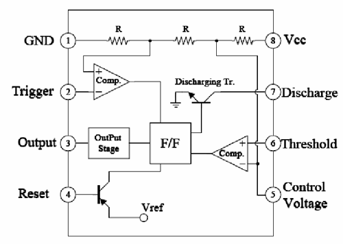
A 1 Hz pulse frequency generator utilizes the widely used timer IC 555 configured as an Astable Multivibrator. The output pulses can be visually indicated by an LED. An Astable Multivibrator, often referred to as a free-running Multivibrator, is...