
Quality Headphone Amplifier
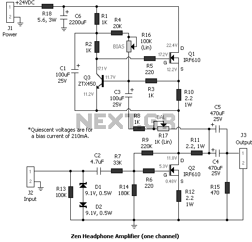
This circuit makes use of feedback, but mainly to establish the working point, since the open-loop performance is quite good. R12 forms a little local feedback. It slightly enhances the circuit linearity, without further dropping the input impedance of the stage.
The main feedback network (R7, R9, R14) takes care of the operating parameters of the circuit, such as working point, gain, bandpass width and, in consequence, input impedance. It has been arranged for a power supply rail of about 24V and for an input impedance of about 35K Ohms (above a good part of the audio spectrum). With those values, the upper frequency limit of the amplifier is about 20KHz (-3dB) and the mid-band gain about 13dB (equivalent to a voltage gain of 4.5).
Changing the gain of the amp is not difficult, if you know what you're doing. Although the gain is controlled by the local feedback network (R7, R9 and R14), changing these values will change the frequency response, and the input impedance too. You must consider all the parameters that change with it. However, for me, this configuration is, at the moment, the best configuration among all for the gain.
If you want to widen the passband, you may change some of the feedback resistors. For example, if R7 is 10K Ohm, R14 is 53K Ohm and R9 68K Ohm, the input impedance now drops down to about 11K Ohm, but the "-3dB" upper frequency limit goes up to about 60-80KHz, at least according to simulations. Anyway, with Grado headphones (I’ve tried with the latest RS-1, SR-325 and SR-80) the passband limitation is not a flaw at all; these phones are quite bright.
R17 (the "Balance" trimmer) is useful to make equal the signal currents (not bias current!) between the HexFets' drains, where the performance of the active current source is optimal. Thus, setting R17 (described later) requires a signal generator and an AC voltmeter and/or an oscilloscope.
R16 sets the bias current, between a few mAs and about 300mA. Although the current sensing system decides how to vary bias current according to the needs of the load, the quiescent bias current must be set manually. The amplifier can deliver about twice the bias current to the load due to the operation of the active current source: Iout = 2 * Ibias. A bias current of 300mA is plentiful, enough for the destruction of the Grado headphones, probably the lowest impedance headphones for high quality listening.
The circuit employs a single-stage Class A MOSFET configuration, which is characterized by its low output impedance and appropriate gain characteristics tailored for high-fidelity audio reproduction. The topology ensures compatibility with various audio sources, particularly low-output devices. The active current source, referenced from Pass' patent, enhances performance by allowing greater output current and minimizing distortion, achieving a theoretical efficiency of 50%.
The amplifier's gain is adjustable, with a design target of at least 10dB to ensure compatibility with various audio sources. The feedback network, composed of resistors R7, R9, and R14, plays a crucial role in defining the amplifier's operational characteristics, including gain, input impedance, and frequency response. The circuit is optimized for a 24V power supply, achieving a mid-band gain of approximately 13dB and a frequency response that extends to 20kHz.
The designer has incorporated provisions for adjusting the gain and bandwidth through resistor selection, providing flexibility while maintaining performance integrity. The balance trimmer (R17) allows for fine-tuning of the signal currents between the MOSFET drains, ensuring optimal performance of the active current source. The bias current, adjustable through R16, is critical for achieving the desired output characteristics, with a maximum setting that can deliver sufficient power for low-impedance headphones.
Overall, this single-stage Class A MOSFET amplifier design is a well-considered solution for high-quality audio applications, particularly for use with high-fidelity headphones, while also emphasizing the importance of careful component selection and adjustment to achieve the best sound quality. It is a single stage class A MOSFET design with the right gain and a low output impedance. Here we don't have the limitations of the Zen amps (at least in the single-stage implementations) regarding speaker compatibility. A single stage topology with correct interfacing values misses very few things in the original music message.
The gain device in the original Zen amplifier is biased by fixed current source. For this amp, I employed an active current source described in Pass' patent no. 5,710,522 (see Zen Variations Part 2). The benefits of an active source include higher output current, lower distortion and 50% theoretical operating efficiency (compared to the 25% efficiency from a fixed source). This type of current source is featured in the Aleph power amplifiers from Pass Labs. I designed this circuit to obtain the best sound from my Grado SR-325 headphones. Portability here was not imperative, so the high power consumption of a real class A amp was not a big drawback. I developed this project at the beginning of 2002 and it was first presented at DIYaudio.com in February 2002.
Since the intellectual property belongs to Pass Labs, this circuit is intended only for notforprofit use, unless the current source topology is altered. I wish to thank Nelson Pass for his open-mindedness and involvement in the DIY audio world; the DIYer community will be always grateful to him!
To obtain the wide compatibility with low-output sources, such as tape decks and tuners, I chose at least 10dB gain for the amplifier. This ensures adequate headroom with almost every CD and CD player I've tried. The amplifier's output current depends on the the output stage bias current, which can be set between a few mA and about 280mA.
If you have an high-impedance headphone, you don’t need to charge the higher current setup, even if at least 100mA bias current is advisable for the best sound quality. This circuit makes use of feedback, but mainly to estabilish the working point, since the open-loop performance is quite good.
R12 forms a little local feedback. It slightly enhances the circuit linearity, without further dropping the input impedance of the stage. The main feedback network (R7, R9, R14) takes care of the operating parameters of the circuit, such as working point, gain, bandpass width and, in consequence, input impedance.
It has been arranged for a power supply rail of about 24V and for an input impedance of about 35K Ohms (above a good part of the audio spectrum). With those values, the upper frequency limit of the amplifier is about 20KHz (-3dB) and the mid-band gain about 13dB (equivalent to a voltage gain of 4.5).
Changing the gain of the amp is not difficult, if you know what you're doing. Although the gain is controlled by local feedback network (R7, R9 and R14), changing these values will change the frequency response, and the input impedance too. You must consider all the parameters that change with it. However, for me, this configuration is, at the moment, the best configuration among all for the gain.
If you want to widen the passband, you may change some of the feedback resistors. For example, if R7 is 10K Ohm, R14 is 53K Ohm and R9 68K Ohm, the input impedance now drops down to about 11K Ohm, but the "-3dB" upper frequency limit goes up to about 60-80KHz, at least according to simulations. Anyway, with Grado headphones (I’ve tried with the latest RS-1, SR-325 and SR-80) the passband limitation is not a flaw at all; these phones are quite bright.
R17 (the "Balance" trimmer) is useful to make equal the signal currents (not bias current!) between the HexFets' drains, where the performance of the active current source is optimal. Thus, setting R17 (described later) requires a signal generator and an AC voltmeter and/or an oscilloscope.
R16 sets the bias current, between few mAs and about 300mA. Although the current sensing system decides how to vary bias current according to the needs of the load, the quiescent bias current must be set manually. The amplifier can deliver about twice the bias current to the load due to the operation of the active current source: Iout = 2 * Ibias.
A bias current of 300mA is plentiful, enough for the destruction of the Grado headphones, probably the lowest impedance headphones for high quality listening. 🔗 External reference
Related Circuits
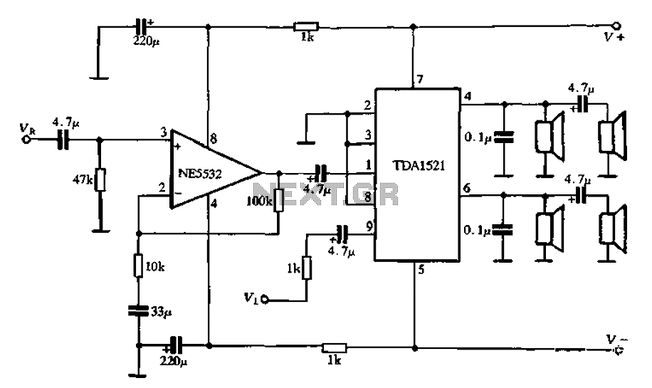
Active speaker with amplifier circuit TDA1521 and NE5532, featuring dual-channel input and dual-channel output. The active speaker circuit utilizes the TDA1521 integrated circuit, which serves as the power amplifier. This IC is designed for high-efficiency amplification, providing a robust output suitable...
Amplifying circuit diagram to enhance the output current and voltage. An amplifying circuit is designed to increase the amplitude of an input signal, resulting in a higher output current and voltage. This type of circuit is commonly utilized in various...
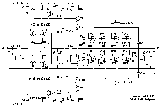
Here I propose a project of an AB class power amplifier, at its simplest, assembled with common components (not very expensive), based on traditional diagrams: a symmetrical differential input stage, a cascode stage driver, and a MOSFET output stage....
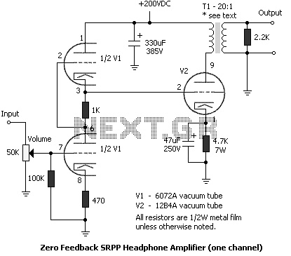
To get a low output impedance I needed to use quite a high step-down ratio (20:1); after all, the amplifier may be used with headphones of lower impedance than the 300 Ohms of the HD600. The output valve is...
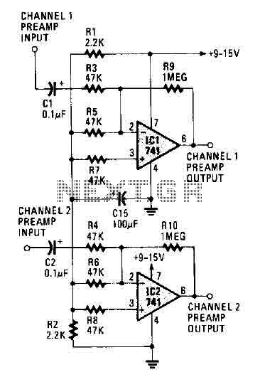
The circuit operates using two 741 operational amplifiers and achieves a gain exceeding 20 dB in each channel. Utilizing a higher-quality op-amp can improve the noise figure and bandwidth. Additionally, the circuit features a sharp roll-off at 20,000 Hertz. This...
This simple audio power amplifier was originally designed for a circuit board workshop conducted by the OSU IEEE Student Group. At the workshop, 20 participants each constructed this amplifier by etching and drilling the single-sided circuit board, soldering all...