
random number generator game
npredictable. Thus the final number displayed in DIS1 through DIS3 is of random nature. The speed with which the number in 7-segment display keeps changing on flipping switch S1 from run` to stop` condition slowly decays before stopping with a random number display. To play this game, one has to obtain three identical numbers in displays DIS1 through DIS3. The contestant would score 1 (one) point if he manages to get a final display of 000`, 2 points for getting 111` display, 3 points for 222`, and so on ”up to ten points for 999`.
He should try to score maximum possible points in fixed numbers of attempts (say, 20 to 25 attempts). Apart from using this circuit as a game for entertainment, one can use it as random number generator for any other application as well.
The decay time with the given component values is around 15 seconds before the display could stop at a final random number. The circuit comprises clock oscillator built around NE555 timer IC4, three-stage clock pulse counter built using three CD4033 ICs (IC1 to IC3), and three 7-segment LED displays (DIS1 to DIS3).
In clock oscillator circuit, NE555 timer IC4 is used in a similar way as a free-running astable multivibrator, the only difference being the additional capacitor C1 introduced between pin No. 7 of IC4 and junction of resistors R22 and R24. When toggle switch S1 is in run` position, both terminals of capacitor C1 are shorted by switch S1 and timer IC4 works as a free-running astable multivibrator.
The operating frequency is in the vicinity of 35 kHz, determined by the value of timing components. When toggle switch S1 is flipped from run` to stop` position, capacitor C1 is introduced in the discharge path of pin No. 7 of IC4 and junction of resistors R22 and R24. At the same time, capacitor C4 comes in parallel with timing capacitor C3 to change the operating frequency of the astable from around 35 kHz to around 65 Hz.
Now capacitor C1 slowly starts charging as it is connected in the discharge path of the timing capacitors C3 and C4. The clock frequency of IC4 gradually reduces and after 15 seconds, when capacitor C1 is sufficiently charged, the oscillating frequency gradually drops and finally it stops oscillating.
Thus, pin 3 of IC4 becomes low. Second part of the circuit comprises three cascaded ICs, IC1 through IC3 (CD4033 decade upcounter cum 7-segment decoder). In conjunction with three 7-segment displays (DIS1 to DIS3), these form a 3-digit clock counter. The clock counting speed is dependant upon the clock pulse frequency of IC4. It is connected to clock input pin 1 of IC1 while chip enable pin 2 of IC1 to IC3 are held low. Thus all clock counter ICs advance by 1 for every positive clock transition. Reset pin 15 of all counter ICs is held low through resistor R25. Thus reset facility is not used in this circuit. Due to persistence of vision, one can not distinguish 0-9 counting in DIS1 to DIS3 when the clock frequency is high.
All 7-segment displays appear to show digit 8, while the red LED1 remains lit continuously, indicating clock counter is in running condition. On sliding toggle switch S1 from run` to stop` position, the counting speed of individual digits falls immediately due to the clock frequency changing to around 65 Hz.
Now, the counting speed will be 65 Hz for DIS3, 6. 5 Hz for DIS2, and 0. 6 Hz for DIS1. This speed of individual digit counting slowly decays, until the counter stops and LED1 stops blinking, and the final count (random numbers) are displayed in DIS1, DIS2, and DIS3. 🔗 External reference
Related Circuits
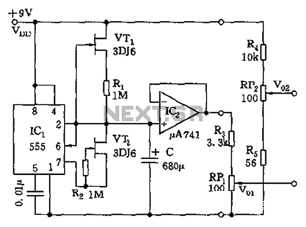
The circuit depicted in the figure is a generator that includes an oscillator, a voltage follower, a zero amplitude adjustment, and a zero shift circuit. It is utilized as a self-balancing recorder for testing signals. The output signal ranges...
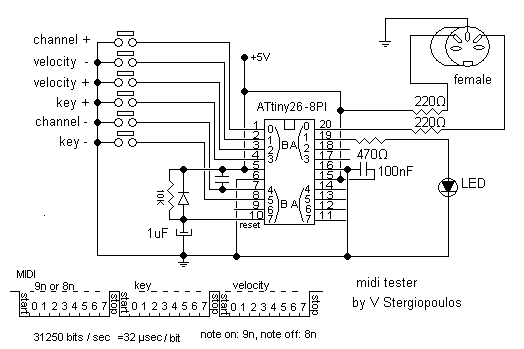
This circuit based on ATtiny26 but it could be anyone microcontroller of AVR family. Produce stable one MIDI tone and you can change it by press some keys like to change midi channel 0-15, velocity 0-127, pitch 0-127. It...
Why an electronic cricket? Many people enjoy the sound of crickets, especially those living in urban areas. This electronic cricket circuit operates in pulses, creating a similar sound. The electronic cricket circuit is designed to replicate the natural sound of...
This circuit is designed to demonstrate high-frequency high voltage, capable of producing approximately 30 kV, depending on the transformer utilized. It is cost-effective and simple to construct, primarily using a standard TV flyback transformer. The circuit can power lasers,...
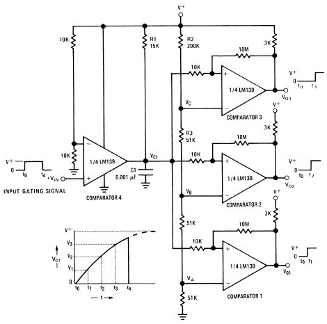
A measure delay generator, also identified similarly to a sequence generator, is a device that provides output signals at specified time intervals from a time reference. It automatically resets when the input signal returns to ground. The schematic illustrates...
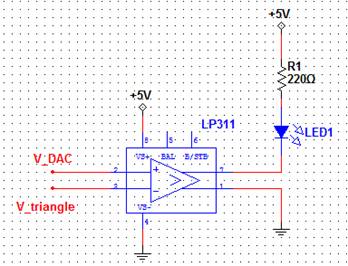
A pulse-width modulated (PWM) signal can be generated using a triangle wave and a comparator. The digital-to-analog converter (DAC) serves as the input signal, and the resulting output signal's duty cycle will be proportional to the input voltage. This...