
Remote Control Mains Switch
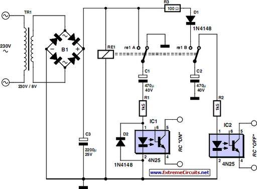
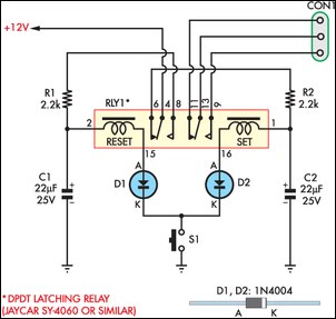
When the lady operates the pull cord or light switch to turn on the light, mains voltage is applied to the transformer, activating the relay, which charges capacitor C1. While C1 is charging, a small current flows through optocoupler 1, simulating a press of the "on" button on the remote control. This action turns on the power point to which the standing lamp is connected, thereby illuminating it. Simultaneously, capacitor C2 is charged. If the lady pulls the cord again or operates the switch near the door, the relay de-energizes, causing C2 to discharge through optocoupler 2, which operates the "off" contact of the remote control, turning off the lamp. The remote control continues to operate from its standard battery, and the white enclosure is mounted on the ceiling in place of the light fixture. Diode D1 ensures that C1 discharges when the relay is de-energized, while D2 prevents C2 from discharging through the relay, allowing it to discharge only through optocoupler 2.
To construct this circuit, the following components are required: a wireless power point, a prototyping board, a relay, two capacitors (C1 and C2), two 4N25 opto-couplers, and two diodes (D1 and D2). The circuit should be designed to ensure that the relay can handle the load of the standing lamp while providing isolation between the mains voltage and the low-voltage control circuit. The use of opto-couplers allows for safe interfacing between the high-voltage and low-voltage sections of the circuit. Proper attention should be paid to the polarities of the components, particularly the opto-couplers and capacitors, to ensure reliable operation. The enclosure should be securely mounted to prevent accidental disconnections or damage. This circuit not only enhances the convenience for the elderly lady but also ensures safety and functionality in her living space.As the only electronics engineer in my family and circle of friends, it is sometimes not possible to evade an appeal for help. This time the request came from a friendly elderly lady in a retirement home. In her room the light switch by the door and the pull cord above the bed operate the light fitting on the ceiling in the middle of the room.
How ever, she would prefer that her standing lamp was operated by these switches instead, since she does not actually have a light fitting mounted on the ceiling. This standing lamp has an on/off switch in the power cord and is plugged into a power point. However, it stands rather far from the bed so that she always has to find her way in the dark. A wireless operated power point is not really a consideration, because it is just a matter of time before the remote is lost.
Or maybe not Behold a feasible circuit. Buy a wireless power point and an enclosure that is big enough for the remote control and a small piece of prototyping board. On the proto-typing board build the circuit according to the accompanying schematic and (carefully) open the remote control and solder wires to the push buttons for on` and off`.
Measure if these are polarised and if that is the case connect them to the 4N25 opto-couplers as shown in the schematic, where pin 5 has a higher voltage than pin 4. The operation is as follows. The lady operates the pull cord or light switch to turn the light on. This causes the mains voltage to be applied to the transformer. The relay is activated which charges C1. While C1 charges, a small current flows through optocoupler 1. The result is that the on` button on the remote control is pressed. The remote control switches the corresponding power point on and to which the standing lamp is connected.
The standing lamp will therefore now turn on. Capacitor C2 is charged at the same time. If the lady pulls the cord again, or if she operates the switch near the door, the relay will de-energize and C2 discharges across optocoupler #2. This operates the off` contact of the remote control and the light goes out. The remote control continuous to operate from its normal battery and the white enclosure is attached to the ceiling in place of the light fitting.
Diode D1 ensures that C1 is discharged when the relay de-energises. D2 ensures that C2 cannot discharge across the relay, but only across optocoupler 2. 🔗 External reference
Related Circuits
The mains supply can be conveniently reduced with no heat dissipation by the reactance of C1; then rectified by D1 (1N4007) and D2 (1N4007) and clamped to 24V. The circuit operates by utilizing the reactance of capacitor C1 to reduce...
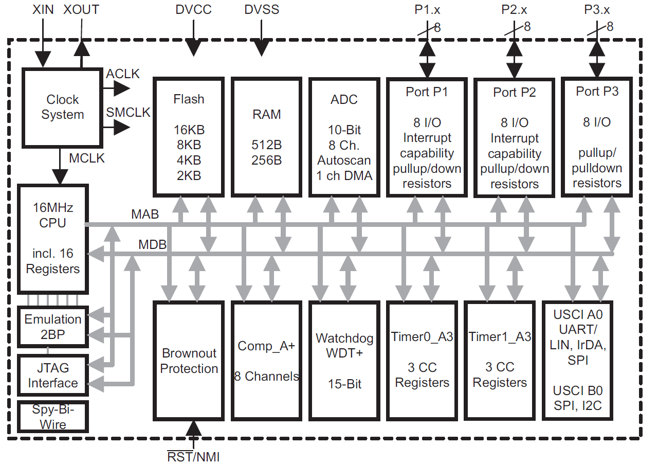
This module provides an overview of the MSP430 microcontroller, instructions on how to read its data sheet, and guidance on selecting the appropriate model for various applications. It is part of a textbook aimed at helping seniors choose Texas...
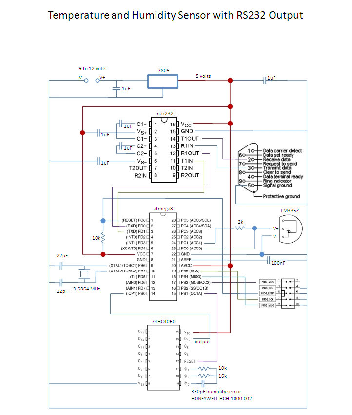
This is an affordable method for measuring temperature and humidity with a computer interface, designed as an entry-level project for high school students on a limited budget. The project involves the integration of a temperature and humidity sensor, such as...
Imagine three or four small engines operating on the same track loop while maintaining a safe distance from one another. Many enthusiasts have attempted this with radio-controlled engines, but it often becomes a challenge to keep them separated, especially...
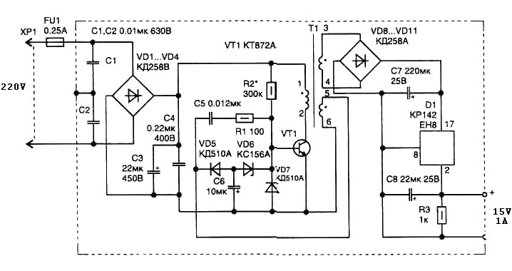
The pulse transformer T1 utilizes a ferrite core, specifically M2500NMS-2 or M2000NM9, with dimensions of Sh5h5 (cross-section of the magnetic coils at 5G—5 mm with a center gap). The winding wire is of type PEL-2. The primary winding consists...
This circuit enables an SPST momentary pushbutton to function as a push-on push-off switch by utilizing a DPDT latching (bi-stable) relay. It was designed to allow a single pushbutton switch on the dashboard of a vintage car to provide...