
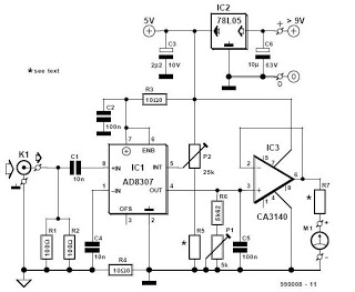
RF Decibel Meter
The zine serves as a comprehensive resource for individuals interested in electronics, providing a wide array of circuit diagrams that illustrate various electronic components and their interconnections. It includes detailed DIY projects that empower users to build their own electronic devices, fostering hands-on learning and experimentation. Each project is designed to cater to different skill levels, from beginners to advanced practitioners, ensuring accessibility for all.
In addition to practical projects, the zine offers electrical data sheets that provide essential specifications and characteristics of various electronic components. This information is crucial for understanding component behavior and selecting the right parts for specific applications. Furthermore, the inclusion of microcontroller projects highlights the growing importance of programmable devices in modern electronics, offering insights into coding and interfacing techniques.
Overall, this zine is an invaluable tool for anyone involved in the electronics field, whether for educational purposes, professional development, or personal interest. It encourages creativity and innovation while providing the foundational knowledge necessary to navigate the complexities of electronic design and implementation.This is a zine dedicated to electronics circuit diagrams, diy (do it yourself) electronics projects, electrical electronics data sheets, and micro controller projects for hobbyist, students, consultants and product designers. 🔗 External reference
Related Circuits
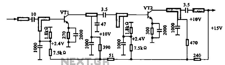
An IF pre-amplifier circuit is presented in a distributed-parameter microstrip configuration. It operates within the frequency range of 950 to 1,470 MHz. The output impedance is approximately 75 ohms. The power supply for the circuit is connected to the...
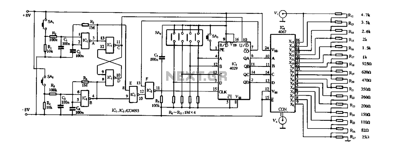
Figure 4-14 illustrates a digital integrated circuit featuring 16 preset potentiometers for Siniperca electronic circuits. The circuit comprises three main components: an input controller, a presettable counter, an analog electronic switch, and a resistor network. It includes a push-button...
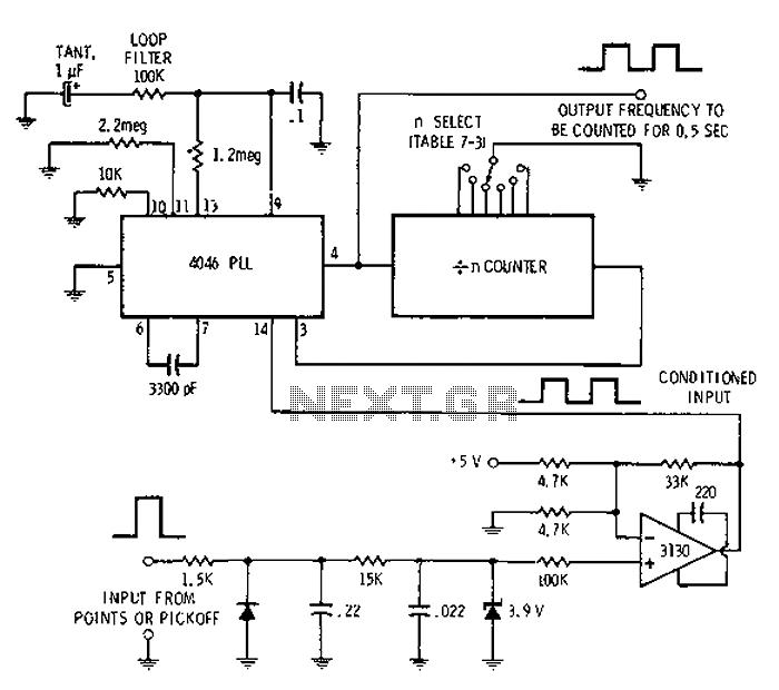
Automotive engine pulse points or other sensors are filtered using the transmission device 3130 CMOS operational amplifier, which functions as a comparator to fulfill the input conditions. The pulse subsequently flows into a 4046 phase-locked loop (PLL) N-counter, which...
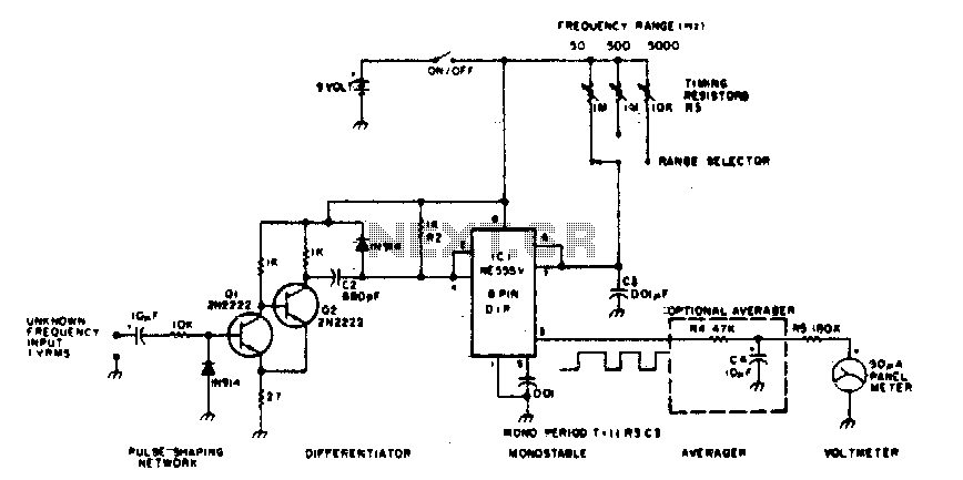
The 555 timer is utilized in a monostable multivibrator circuit that generates a pulse of fixed time width, which is activated by an unknown input frequency. The 555 timer in a monostable configuration operates by producing a single output pulse...
This is a circuit schematic diagram for VU meters. The circuit is controlled by the IC TL072 and follows a measurement circuit as per the National general application. The input circuit around IC1 is designed for adaptation and amplification...
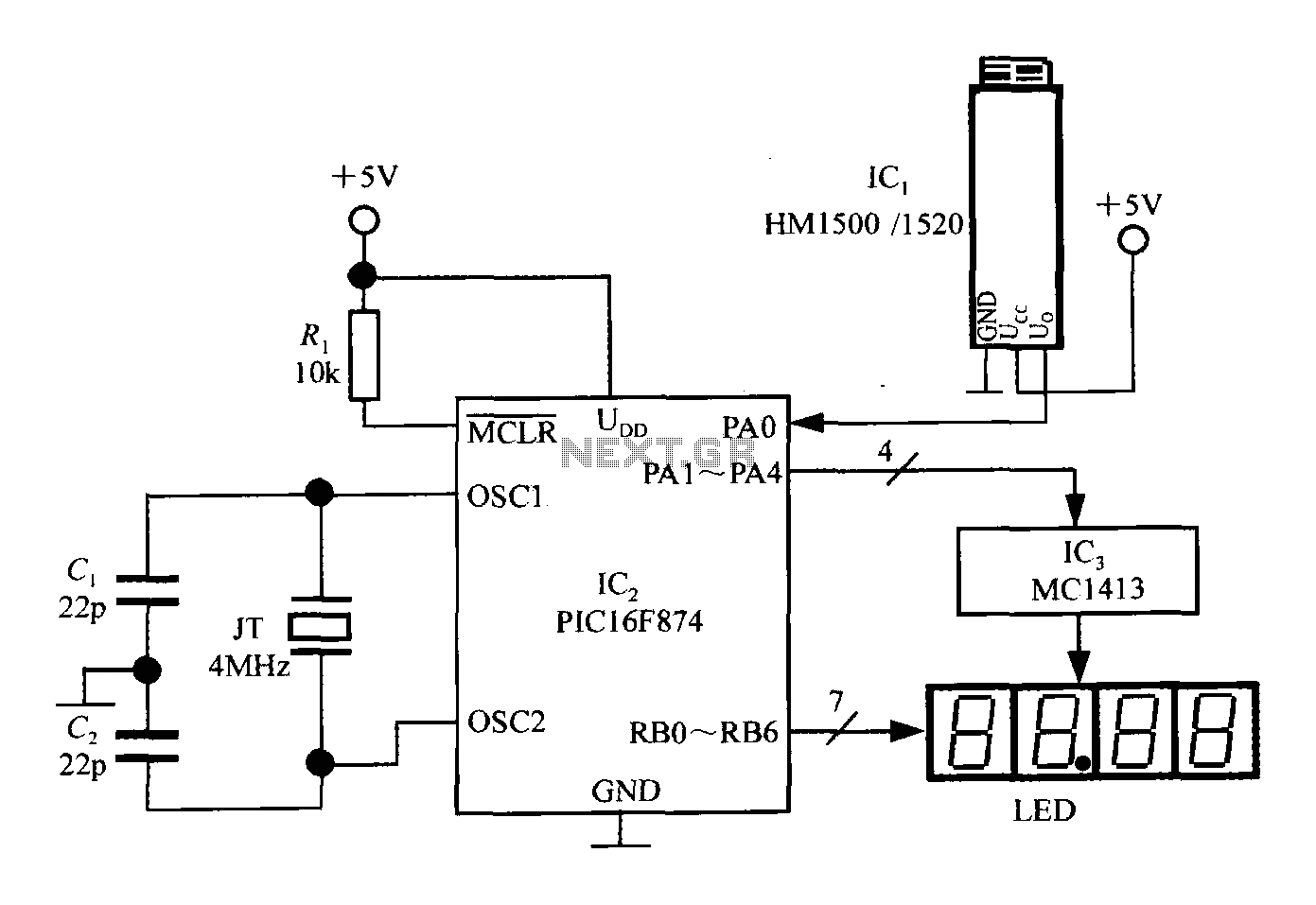
An intelligent humidity meter circuit utilizing the HM1500/1520 humidity sensor and a microcontroller configuration. The circuit operates on a +5V power supply and incorporates four common cathode LED digital displays. It employs three integrated circuits: IC1 is the HM1500/1520...
Warning: include(partials/cookie-banner.php): Failed to open stream: Permission denied in /var/www/html/nextgr/view-circuit.php on line 713
Warning: include(): Failed opening 'partials/cookie-banner.php' for inclusion (include_path='.:/usr/share/php') in /var/www/html/nextgr/view-circuit.php on line 713