
RF Switch with Pin Diode
The PIN diode RF switch is designed to efficiently route RF signals in the VHF (Very High Frequency) and UHF (Ultra High Frequency) bands. The switch utilizes PIN diodes, which are characterized by their ability to handle high-frequency signals with minimal insertion loss and excellent linearity. This capability makes them suitable for applications where signal integrity is paramount.
In the circuit, the PIN diodes are configured in a manner that allows for low-resistance paths when forward-biased, enabling the RF signals to pass through with minimal attenuation. Conversely, when reverse-biased, the diodes present a high impedance, effectively isolating the unused paths and preventing signal leakage.
The switch can be controlled using various methods, including analog control voltages or digital signals, depending on the design requirements. The control circuitry typically includes a microcontroller or a logic gate arrangement that determines the biasing of the diodes based on the desired antenna selection.
Key components of the circuit include RF connectors for input and output, the PIN diodes themselves, biasing resistors, and the control interface. Proper PCB layout is crucial to minimize parasitic capacitance and inductance, which could adversely affect the switch's performance at high frequencies. Additionally, careful consideration must be given to the power ratings of the components to ensure reliable operation under various conditions.
Overall, this PIN diode RF switch is an essential component in RF systems, providing reliable and efficient signal routing for VHF and UHF applications.This PIN diode rf switch is the ideal antenna switch for VHF and UHF and work with the PIN diodes which are special high frequency switching diodes with ve.. 🔗 External reference
Related Circuits
This is a simplified version of the Universal Keypad-Operated Switch. The design has been modified to reduce circuit complexity and the number of components required, resulting in somewhat less secure code functionality. However, it remains adequate for many applications....
This weblog discusses electronic circuit schematics, PCB design, DIY kits, and electronic project diagrams. The circuit diagram presented is for a magnetic proximity switch, which has numerous applications across various fields. The circuit utilizes a magnetic reed switch (S1)...
The DS2715 is a comprehensive NiMH (Nickel Metal Hydride) smart charger solution featuring load detection, making it ideal for cost-effective applications. The DS2715 smart charger integrates several key functionalities designed to enhance the charging process for NiMH batteries. It employs...
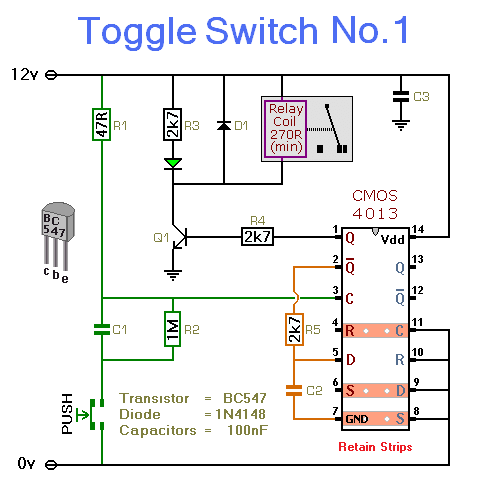
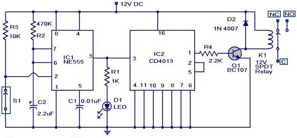
This simple circuit will energize and de-energize a relay at the push of a button. Any type of momentary action push-to-make switch can be used. Pushing the button once will energize the relay. And pushing it a second time...
High-efficiency step-down switching regulators for positive voltages are common; however, negative step-down switching regulators (negative voltage in, negative voltage out, common ground) are less well known, despite their frequent necessity. Setting them up is not particularly challenging, but literature...
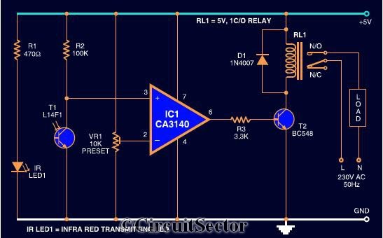
The circuit diagram presented is a highly sensitive wireless relay switch designed to control home appliances such as flush systems and hand dryers. This wireless switch operates without the need for a remote control. It functions by simply moving...