
Wideband Preamp Circuit
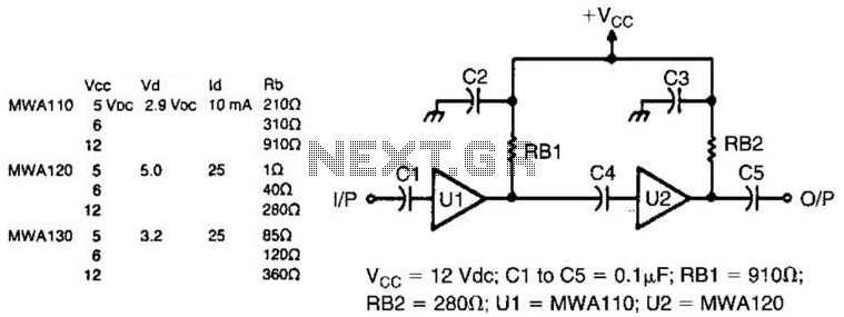
The Motorola MWA series, specifically the MWA 110, 120, and 130 wideband amplifier integrated circuits (ICs), are designed for high-frequency applications requiring low noise and high gain. These amplifiers are particularly effective in situations where signal integrity is paramount, such as in RF and communication systems. The wideband preamplifier circuit utilizing these ICs is versatile and can be adapted for various applications, from audio processing to signal conditioning in telemetry systems.
When constructing the circuit, it is crucial to minimize the length of the leads connecting the components. Short leads reduce parasitic inductance and capacitance, which can adversely affect the performance of high-frequency circuits. The printed circuit board (PCB) layout is an essential aspect of the design, where the copper shading indicates the areas of copper traces that connect the various components.
In this configuration, a feedthrough wire labeled 'X' is employed to connect to the ground plane, ensuring a stable reference point for the circuit and helping to mitigate noise. The choice of capacitors is also significant; all capacitors in this design are specified as 0.1 µF. This value is commonly used in RF applications due to its effectiveness in bypassing high-frequency noise while maintaining signal integrity.
The overall design emphasizes the importance of a well-thought-out PCB layout and component placement to achieve optimal performance of the wideband amplifier. Proper grounding techniques, including the use of a ground plane and short lead lengths, are critical to minimizing interference and enhancing the reliability of the circuit in real-world applications. Motorola MWA 110, 120, or 130 are wideband amplifier ICs. This wideband preamp circuit can be used in many applications. Keep the leads short when constructing the circuitry. PC board layout (shading represents copper) and parts layout. X is the feedthrough wire to the gound plane. All capacitors are 0.1 uF. Keep all leads short. 🔗 External reference
Related Circuits
Incremental rotation or linear encoders are widely used, but they typically do not provide a direction signal. This design presents a straightforward method to detect forward or reverse direction. Incremental encoders usually generate two output signals, referred to as...
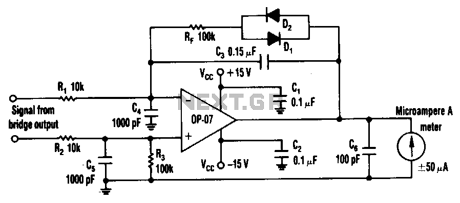
The circuit can utilize any general-purpose, low-offset, low-drift operational amplifier (op amp), such as the OP-07. The differential signal from the bridge feeds into an amplifier that drives a standard, rugged ±50 µA meter. However, near the null point,...

This circuit design for a low current relay is intended for use in battery-operated electronic devices, with an operating current in microamperes (µA). It utilizes a bistable relay and additional components to enable the relay to function similarly to...

This simple alarm timer circuit is constructed using a 4060 integrated circuit, which features a stable oscillator with a relatively wide frequency range. The alarm timer circuit utilizes the CD4060 IC, which combines a low-frequency oscillator and a binary counter....
The most extreme option would be to supply power through a battery pack. A more plausible source would be the car's battery. However, since the objective of the circuit is to activate the buzzer when the headlights are on,...

Utilize this FM antenna amplifier in locations where the reception of FM stations is poor. This circuit is specifically designed for this purpose. The FM antenna amplifier circuit is engineered to enhance signal strength for FM radio stations, particularly in...