
Ringing phone light flasher

The described circuit operates as a telephone ringing indicator, utilizing a combination of an opto-coupler, transistors, and a relay to control an external load. The circuit is designed to respond to the ringing voltage of a telephone line, which typically rises to approximately 72 volts AC when a call is incoming.
The opto-coupler serves a critical role in the isolation of the telephone line from the control circuitry, ensuring safety and preventing damage to sensitive components. When the telephone rings, the increased voltage activates the LED within the opto-coupler. This LED emits light, which is detected by a phototransistor inside the opto-coupler, causing it to conduct.
The output from the opto-coupler is connected to the base of transistor Q1, which acts as a switch. When Q1 is activated by the opto-coupler, it allows current to flow from the collector to the emitter, effectively turning on the relay. The relay is an electromechanical switch that can handle higher power loads, making it suitable for controlling devices such as bulbs or bells.
The load connected to the relay is powered when the relay is energized, providing a visual or audible indication of an incoming call. This circuit can be used in various applications, including home automation systems or as a simple alert mechanism in environments where a telephone is not easily heard.
Safety considerations must be taken into account when designing this circuit, particularly in ensuring that the opto-coupler can handle the voltage levels present on the telephone line and that adequate isolation is maintained throughout the circuit. Additionally, proper component ratings should be selected to accommodate the power requirements of the connected load.When the telephone rings the line voltage rises to 72 volts. At this time the LED in the opto-coupler glows and the transistor conducts. Due to this the transistor Q1 conducts. This makes the relay ON. The load connected to the relay whether bulb or bell turns ON. 🔗 External reference
Related Circuits

This dimmer is designed to adjust the brightness of incandescent bulbs from zero to maximum. It achieves regulation from zero using a double delay circuit. The circuit is connected with two terminals, allowing for installation into a switch box...
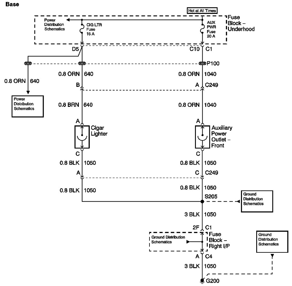
The provided information includes a fuse block diagram with the Auxiliary Power (Aux Pwr) fuse highlighted. It is advisable to check both sides of the fuse using a test light or multimeter to ensure functionality. It is assumed that...

Both microphones, along with the stereo mics SM2 and SM23, utilized a similar basic capsule design akin to the KM54 capsule. According to Klaus Heyne of German Masterworks, the FET KM88 was created to utilize the company's surplus of...

Similar to the previous circuit utilizing the LM358, this design is also cost-effective, priced under 100 rupees. It is a circuit intended for the automatic control of street lights and garden lights. Users do not need to manually turn...
This is basically a flasher circuit modified to turn on and off a bulb instead of a LED. It uses a 555 timer IC working as an astable multivibrator. The flashing rate can be varied from very fast to...

This circuit is a modified flasher designed to control the on and off operation of a bulb instead of an LED. It employs a 555 timer integrated circuit (IC) configured as an astable multivibrator. The flashing frequency can be...