
RS-232 data buffer
The circuit operates as a buffer to enhance the integrity and speed of RS232 signals over long distances, addressing issues related to signal degradation due to poor quality wiring. The two transistors, Q1 and Q2, are configured in a push-pull arrangement, allowing for efficient signal amplification while maintaining low distortion. The choice of resistor R2 is critical as it determines the output current capacity and ensures proper impedance matching with the connected cable. The selection of a 140-ohm resistor was based on empirical testing, optimizing both performance and thermal management.
The design incorporates a D25 connector for ease of integration with existing RS232 interfaces. Power is supplied through pins 9 and 10, which are typically used for control signals in RS232 communications, allowing for a neat and compact installation without the need for additional power connectors. This method of power supply is particularly advantageous in portable or space-constrained applications.
The circuit's ability to handle current pulses up to 1A while limiting continuous current to around 100 mA ensures that it can accommodate varying loads without compromising performance. This capability is essential for maintaining reliable communication in environments where signal integrity is paramount.
Overall, the buffer circuit effectively doubles the throughput of RS232 communications over long cable runs, making it a valuable solution for enhancing data transmission in applications with similar constraints. Its design reflects practical considerations for component availability, thermal management, and ease of implementation, making it a suitable choice for similar applications in various settings.This is a simple serial port buffer circuit I designed for a friend to speed up his SLIP connection in campus computer network "TRINET" of Helsinki University of Technology. The problem in the network was that the RS232 commections from rooms to terminal server were long and made of bad quality wiring.
The circuit is a simple buffer which adds more driving capacity to PC serial port for the signal to go succesfully from PC computer to terminal server (other direction had no problems). The computer is connected to connector CON1 and the buffered output is available ar CON2. With this circuit the speed of RS232 connection to termial server could be succesfully raised for 9600 bps to 38400 bps.
The circuit is basically a two transistor buffer consistong of transistors Q1 and Q2 which can drive up to 1A current pulses, but the maximum putput current of the circuit is limited by resistor R2. Value R2 was experimentally selected by testing resistor values in range of 22 ohm to 270 ohm and value 140 ohm gave best results (it provides quite good impedance matching to cable used).
It is a good idea to use at least 1W resistor in place of R2 to make sure that it does not overheat in output short circuit situation (RS232 devices must withstand that to meet the standard). Worked nicely in one special application, doubled the line throughput Availability of components: Widely available components at the time when the circuit was built Design testing: Circuit was in constatant use by my friend for over a year Applications: Maximizing RS-232 line throughput on long cable runs Power supply: +-12V DC power supply 80 mA The circuit was designed to be a compact box which is powered through D25 connector as some commercial RS232 buffer circuits.
The idea is to feed the power to the buffer unit through serial port voltage test pins 9 and 10. The power was taken from an external power supply (cheap universal wall transformer) and wired to the D25 connector by modifying the cable connected between computer and the buffer circuit. The circuit in this configuration takes maximally continuous current of about 100 mA. 🔗 External reference
Related Circuits

The diagram below shows 5 switches connected to the 5 input lines of the parallel port. An external 5 volt power supply is used to provide high logic levels to the input pins when the switches are open. Three...

The pressure transmitter circuit data acquisition system utilizes the 1B31, an 18-bit A/D converter (AD1170), and an MCS-51 microcontroller. The configuration, as depicted in the accompanying diagram, features a full-scale output voltage of 10 mV from the pressure transmitter...
The VCA project demonstrates the use of the VCA_Setup and VCA_Data components in ADS. These components belong to the ADS behavioral model suite located under the System - Data Models palette. The schematic "Amp_wBothMatches_setup.dsn" is designed to extract circuit-level...
The MSF transmitter transmits time data bit-by-bit over 60 seconds each minute by modulating a 60 kHz carrier frequency. It employs a continuous wave (CW) signal. Two bits are sent every second through variations in the duration and number...
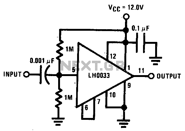
The input is DC biased to the mid-operating point and is AC coupled. Its input impedance is approximately 500K ohms at low frequencies. For DC loads referenced to ground, the quiescent current is increased by the load current set...
Visit eBid United Kingdom, the online marketplace without fees - buy and sell today. eBid United Kingdom serves as an online marketplace that facilitates buying and selling transactions without imposing fees on its users. This platform offers a user-friendly interface...
Warning: include(partials/cookie-banner.php): Failed to open stream: Permission denied in /var/www/html/nextgr/view-circuit.php on line 713
Warning: include(): Failed opening 'partials/cookie-banner.php' for inclusion (include_path='.:/usr/share/php') in /var/www/html/nextgr/view-circuit.php on line 713