
rs232 with opto isolation

The circuit design is centered around the use of an opto-isolator to achieve electrical isolation between the PC and the connected sensors and actuators. This isolation is critical for protecting sensitive components from voltage spikes and noise that may originate from either side of the connection. The opto-isolator, such as the 4N35, serves as a key component in this setup, allowing for safe signal transmission while maintaining isolation.
For applications that may require different specifications, the MCT2E and CNY17-3 opto-isolators can be employed, each with their own characteristics that may necessitate adjustments in the circuit. The MCT2E, with a lower current transfer ratio, may require modifications to ensure that the output signal is adequately driven. In contrast, the CNY17-3 and similar devices provide higher current transfer ratios, allowing for a more straightforward implementation.
Powering the circuit from the PC without imposing additional load on its power supply is a significant advantage, as it minimizes the risk of overloading the PC's internal circuitry. Care must be taken to avoid applying voltages exceeding 5V to the PC connectors, as this could lead to irreversible damage, particularly in older models that are less robust than contemporary hardware.
The isolation barrier provided by the opto-isolator is enhanced by proper PCB design. By ensuring that there are no copper traces connecting the high-voltage side to the low-voltage side, and by maintaining appropriate spacing between components, the design can achieve isolation ratings of up to 1kV. This is particularly important in applications where high voltages may be present.
The inclusion of LEDs to indicate data transmission activity is a useful feature for debugging and monitoring purposes. However, once the circuit has been tested and validated, these indicators can be omitted to simplify the design further.
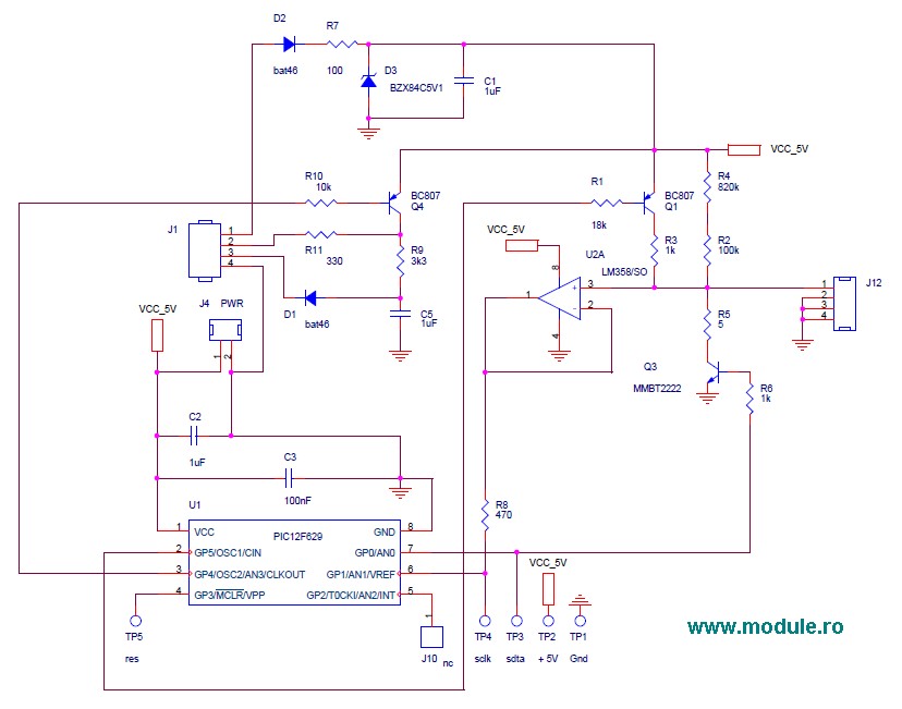
Lastly, the conversion of RS232 signal levels to drive the opto-isolator LEDs is a crucial aspect of the design. The RS232 standard operates with voltage levels that are not compatible with TTL logic levels, thus requiring careful consideration in the design to ensure proper operation and signal integrity. This circuit serves as a robust solution for interfacing with serial communication systems while providing the necessary isolation and protection for both the PC and peripheral devices.Even though i had isolation at the sensors and actuators to make doubly sure the PC also has been isolated. There are chips that are available for this purpose, The circuit above is built with discrete and passive components except for the opto 4N35.
You can use MCT2E and CNY17-3 Optos too. For MCT2E some tweak may be needed as current transfer ra tio is 20, for the other two CTR is 100 so above design will work. The circuit derives power from PC but does not load the PC supply. Any voltage above 5V applied to the PC connectors may lead to damage of motherboard in PC. Old PCs were more vulnerable but PCs today maybe a bit rugged at the Ports. Due to internal current limits and clamping. The VCC, VDD and Agnd are derived from PC no other power needs to be applied on PC side of opto. On uC side of opto the uC power supply lines +5 and gnd has to be used. There is no copper link between the two sides and depending on opto a 1KV isolation is possible if PCB is well designed. The PCB should show the visual isolation above and components should be laid on separate areas of PCB to prevent creepage.
The LEDs are to indicate the port activity Rx and Tx, they are not required once testing is over. The circuit can be simpler, but this worked for me and it is not tested at very-high buad rates. The levels of RS232 are not TTL like 0-5 we have both polarities +10 and -10. The circuit has to change that to drive the Opto Leds. Read more about serial port here. 🔗 External reference
Related Circuits
Unlike most surface-mounted device (SMD) resistors, SMD ceramic capacitors do not have their values marked. To determine the value of these capacitors, a capacitance meter is required. SMD ceramic capacitors are widely used in modern electronic circuits due to their...
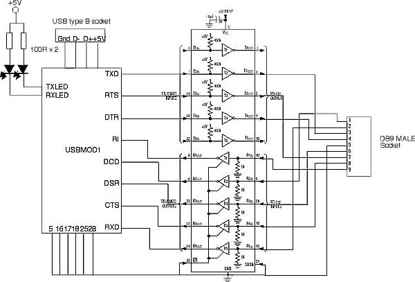
The FT8U232AM requires a small number of external components to produce a device that converts USB to TTL level RS232 signals. All that is needed is a TTL to RS232 converter to provide the 12V RS232 logic levels. The...
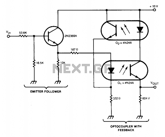
A circuit stabilizes the current-transfer ratio (CTR) of an optically coupled isolator used as a linear transducer. The optocoupler produces a voltage output that is proportional to, but electrically isolated from, the voltage input. However, the output voltage is...
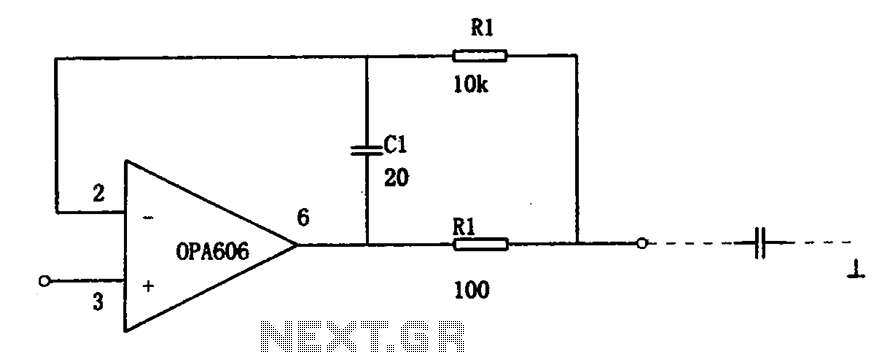
The isolation buffer circuit for capacitive loads is illustrated. When using an external operational amplifier (op-amp) with capacitive loads, the stability of the circuit is significantly affected, which leads to a degradation in dynamic performance. The circuit effectively demonstrates...
A standard serial interfacing for PC, RS232C, requires negative logic, i.e., logic 1 is -3V to -12V and logic 0 is +3V to +12V. To convert a TTL logic, say, TxD and RxD pins of the uC chips, thus...
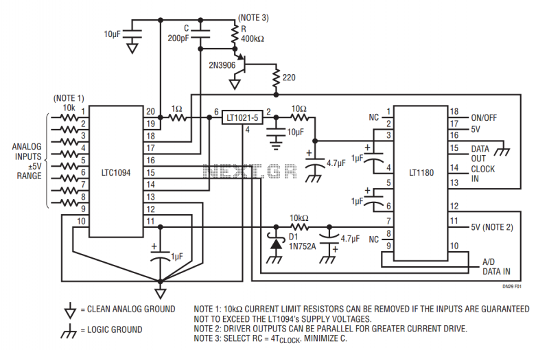
The LT1180 RS232 transceiver includes a charge pump which produces low ripple supplies with sufficient surplus current to drive a CMOS A to D converter and precision voltage reference. The circuit operates from a single 5V supply and draws...