
Sawtooth Wave Generator
The sawtooth wave generator is an essential circuit used in various applications, including audio synthesis, signal modulation, and timing applications. The fundamental operation of this circuit is based on the linear charging and rapid discharging of a capacitor.
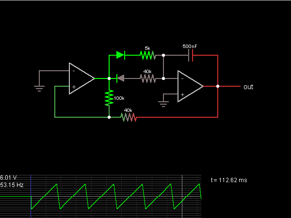
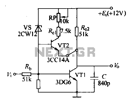
The core components typically include a resistor, a capacitor, and an operational amplifier or a transistor, depending on the design requirements. The capacitor charges through the resistor, creating a linear voltage increase over time. Once the voltage across the capacitor reaches a predefined threshold, a comparator or a transistor switches states, rapidly discharging the capacitor to initiate the next cycle of the waveform.
The frequency of the sawtooth wave can be adjusted by varying the resistor and capacitor values, allowing for flexibility in output frequency. The output can be taken from the junction of the resistor and capacitor or directly from the output of the comparator or transistor.
In a typical schematic, the power supply is connected to the operational amplifier or transistor, providing the necessary voltage levels for operation. The output waveform is characterized by a linear rise followed by a sharp drop, which is the defining feature of the sawtooth wave.
This circuit can be simulated using electronic circuit simulation software, which provides a visual representation of the waveform and allows for real-time adjustments to component values. This simulation capability aids in understanding the behavior of the circuit under various conditions and assists in troubleshooting and optimization before physical implementation.This is the Sawtooth Wave Generator circuit diagram with the detailed explanation of its working principles. The electronic circuit simulator helps you to design the Sawtooth Wave Generator circuit and to simulate it online for better understanding..
🔗 External reference
Related Circuits
A sawtooth wave generator circuit using a 555 IC is presented in the article below. The frequency equation is provided with the supply voltage Vcc. The sawtooth wave generator circuit utilizing a 555 timer integrated circuit (IC) is a fundamental...
The timing must be exact to get those high voltage spikes. I used a tiny magnet on the rotor, that triggered a reed switch allowing the relay to pulse the energy from the recovery coil to the primary battery....
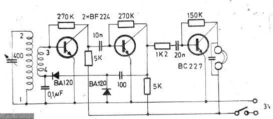
Oscillating circuits (coils) are constructed on a ferrite bar. For long wave reception, winding "1-2" consists of 135 turns, while winding "3-4" consists of 20 turns. For medium wave reception, winding "1-2" has 75 turns, and winding "3-4" has...
Various sawtooth voltage generators utilize the principle of capacitor charging and discharging to produce sawtooth waveforms in both forward and reverse directions. A simple sawtooth voltage generator circuit is straightforward in design; however, it suffers from poor linearity in...

A tapped-coil Colpitts oscillator is utilized at Q1 to deliver four tuning ranges: 1.7 to 3.131 MHz, 3.0 to 5.6 MHz, 5.0 to 12 MHz, and 11.5 to 31 MHz. A Zener diode (D2) is incorporated at Q1 to...
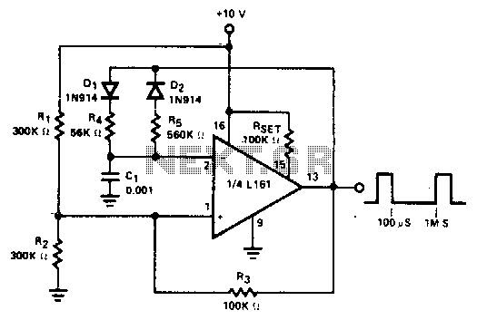
The duty cycle of the output pulse is equal to R4/(R4 + R5) x 100%. For duty cycles of less than 50%, D1 can be eliminated and R2 increased. R4(eff) is the effective value of R4 in the circuit,...