
Schematic of Philip Hoylands Beam Ray Laboratory Rife Machine

The Gruner Schematic represents a key component of Philip Hoyland's Beam Ray Laboratory Rife Machine, which is designed for the application of electromagnetic frequencies in therapeutic settings. The Rife Machine operates on the principle that specific frequencies can target and eliminate pathogens, thereby promoting healing and wellness.
The schematic typically includes various electronic components, such as oscillators, amplifiers, and filters, which work together to generate the desired frequency outputs. The oscillator is crucial as it produces the base frequency that can be modulated to match the resonant frequency of specific pathogens. Amplifiers are employed to boost the signal strength, ensuring that the frequencies can effectively penetrate biological tissues.
Additionally, the design may incorporate a tuning mechanism, allowing the operator to adjust the output frequency precisely. This tuning capability is essential for tailoring the treatment to individual patient needs and the specific conditions being addressed.
Power supply circuits are also integral to the schematic, providing the necessary voltage and current to the various components. Safety features, such as fuses and circuit protection, are typically included to prevent damage to the device and ensure user safety.
Overall, the Gruner Schematic serves as a foundational blueprint for the construction and operation of the Beam Ray Laboratory Rife Machine, emphasizing the integration of electronic components to achieve therapeutic outcomes through frequency application.Chapter The Gruner Schematic of Philip Hoyland`s Beam Ray Laboratory Rife Machine, There is another feature that the Beam Ray Laboratory Rife Machine had.. 🔗 External reference
Related Circuits
Individuals who frequently utilize battery-operated devices or require a negative voltage from a single positive source will find the following converter beneficial. This circuit can convert a 9 V positive battery voltage to a negative voltage using the well-known...
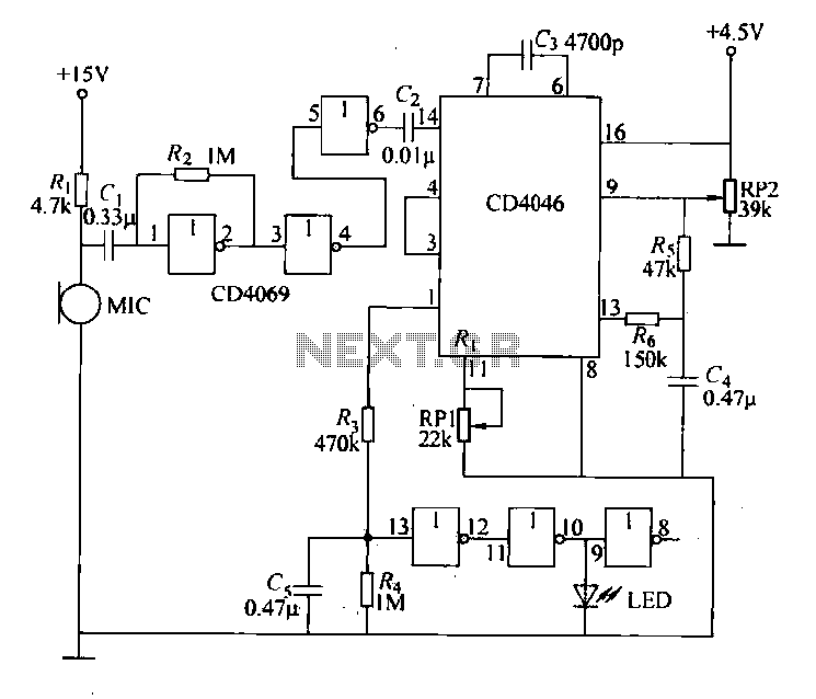
Each issue produces a specific frequency of sound, and the audio remote control will switch states based on these frequencies. The circuit is designed to detect other frequencies emitted by environmental sounds with strong anti-interference capabilities. The circuit operates...
In this circuit, a 74HC14 hex Schmitt trigger inverter is used as a square wave oscillator to drive a small signal transistor in a class C amplifier configuration. The oscillator frequency can be either fixed by a crystal or...
This document serves as a supplementary guide to numerous existing resources that detail the construction of a USB charger. It is assumed that the reader possesses a basic understanding of electronics. The construction of a USB charger typically involves a...
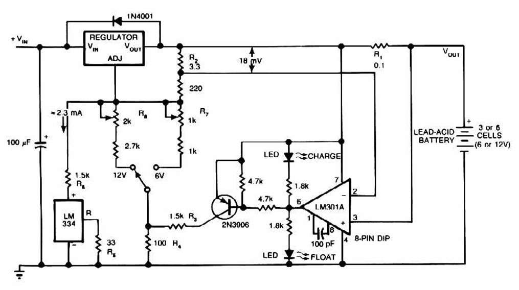
The schematic for this charger is straightforward. It is designed to charge a Gel Cell or other lead-acid types. This simple battery level monitor circuit can indicate the charging process in a 12 Volt lead-acid battery or tubular battery....
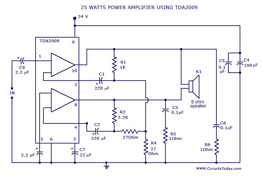
Power amplifier circuit diagram with schematics. This simple audio power amplifier circuit is designed for 25 watts output power using TDA 2009 IC, which has two channels (stereo), 12.5 W for each channel. The described power amplifier circuit utilizes the...