
SDR Soundcard Tester
To implement this testing procedure, a straightforward circuit can be constructed around the NE555 timer IC configured in astable mode, generating a square wave output. The output frequency can be adjusted via a variable resistor, allowing the user to explore the frequency range from 10 kHz to 20 kHz. The circuit's output is then connected to the soundcard input, while an SDR software application is executed on the PC. The software will visualize the frequency spectrum, providing insights into the soundcard's performance. The presence of harmonics at 30 kHz and 45 kHz can be monitored to assess the soundcard's ability to handle higher frequencies without distortion. The inclusion of RC networks at the output enables phase shifting, crucial for testing the I-Q processing capabilities of the soundcard. This setup not only facilitates the evaluation of the soundcard's specifications but also serves as a practical learning tool for understanding digital signal processing in the context of SDR applications.The key to using a soundcard successfully in digital signal processing or digital radio applications lies principally in the characteristics of the soundcard itself. This applies in particular to SDR (software de ¬ ned radio) programs that turn your PC into a top-class AM/SSB/CW receiver, assuming your soundcard cooperates.
If you want to experim ent with SDR and avoid a lot of frustration, it is worth checking ¬ rst whether the PC soundcard you plan to use is suitable. There are three essential elements to success: Many laptops have only a mono microphone input, sometimes also rather limited in bandwidth.
In this case it may be possible to use an external USB soundcard. Most desktop PCs these days have an internal integrated soundcard, although some of these do not feature an anti-aliasing ¬ lter. Attempts to disable the integrated soundcard and replace it with a better one often meet with failure; again, an external USB soundcard is a possible solution.
To avoid guesswork, the best way to proceed is to test the soundcard using this very small circuit. This will help to diagnose any problems and will help determine whether the card is suitable for use with an SDR program. Figure 1 shows a simple square-wave generator built around an NE555 timer IC. At the output is a 15 kHz signal rich in higher harmonics. Using this we can determine whether or not the soundcard can process the harmonics at 30 kHz, 45 kHz and so on.
An anti-aliasing filter at the soundcard input should attenuate all signals above 24 kHz. The frequency of the test generator is, within limits, dependent on its supply voltage. Using an adjustable power supply, a frequency range from 10 kHz to 20 kHz can therefore be covered. There are two RC networks at the output of the test circuit, a high-pass filter and a low-pass filter, acting as simple phase shifters. At the basic frequency of 15 kHz these provide a total phase difference of 90 degrees, corresponding exactly to the typical situation at the output of an SDR receiver circuit using an I-Q mixer: signals at the same frequency but differing in phase.
To test the soundcard we need an SDR program running on the PC as well as the circuit of Figure 1. Suitable software includes SDradio (available for download from When things are running correctly, the screen should display just two signals: the wanted signal at 15 kHz and a weaker image at 15 kHz (Figure 2). Suppression of the image may not be particularly good as the test circuit does not have very high phase and amplitude accuracy.
If, however, the signals have the same level, there is a problem in the processing of the two channels: it is probable that the soundcard only has a monophonic input. If there is no anti-aliasing filter at the input of the soundcard the spectrum will show a large number of extra lines (Figure 3): it is easy to work out which harmonic corresponds to which alias frequency.
The results obtained using an I-Q receiver were grim: frequencies all the way out to 100 kHz were wrapped into the audible range, resulting in bubbling, hissing and whistling. In theory it would be possible to add an anti-aliasing filter to the output of the receiver to allow use with soundcards that are not equipped with such a filter.
In practice, however, it is not easy to achieve the required sharp cutoff and symmetry between the two channels. A typical soundcard has a low pass filter set at 24 kHz which by 27 kHz is already attenuating the signal by some 60 dB.
This is only practical using digital ¬ lters; an adjustable analogue circuit to achieve this performance would be so complex that the simplicity benefits of SDR receiver technology would entirely evaporate. 🔗 External reference
Related Circuits
A simple device designed for quickly checking common infrared remote controls can be beneficial for electronics enthusiasts who often need to repair or test these widespread devices. A reliable circuit was created using a few components: the LED will...
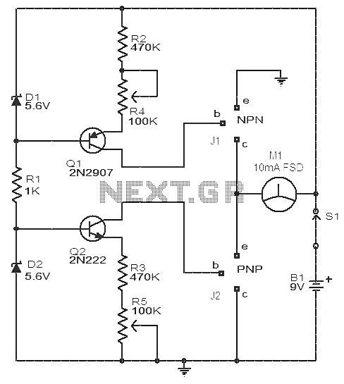
This circuit is a simple device for testing the hfe (current gain) of both PNP and NPN transistors, with the capability to measure hfe values as high as 1000. It operates using two constant current sources formed by transistors...
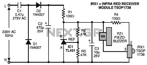
The remote control tester circuit is a simple and easy-to-construct device for verifying the basic operations of an infrared remote control unit. It is low-cost and designed around infrared technology. The remote control tester circuit typically consists of a photodiode...

This circuit is designed to detect the approximate percentage of salt contained in a liquid. After careful calibration, it provides a quick, rough indication of the salt content in liquid foods for dietary purposes. The circuit utilizes the LM324...
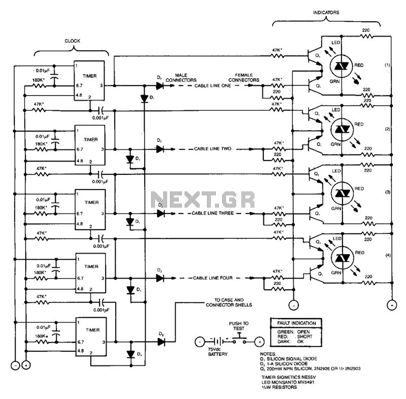
This compact tester checks cables for open-circuit or short-circuit conditions. A differential transistor pair at one end of each cable line remains balanced as long as the same clock pulse generated by timer IC appears at both ends of...
The Software Defined Radio (SDR) hardware, in its most basic configuration, includes a wideband switched balanced mixer and a low noise LF amplifier. This straightforward hardware demonstrates remarkable sensitivity and linearity, making it suitable for both testing and regular...