
SEQUENTIAL AC FLASHER

The described circuit operates on a sequential triggering mechanism using a ring counter configuration. The primary components include silicon-controlled rectifiers (SCRs) Q3, Q4, and Q5, which are arranged to create a ring counter. This configuration allows for a cyclic operation where each SCR is triggered in succession. The oscillator, represented by Q2, generates a clock signal that initiates the triggering sequence.
The 0.2 F capacitor plays a crucial role in the commutation process. When an SCR is triggered, the capacitor discharges, providing the necessary energy to turn off the previously activated SCR. This ensures that only one SCR is conducting at any given time, maintaining the integrity of the sequential operation.
The triacs Q6, Q7, and Q8 are employed to control the power supplied to lamps 1, 2, and 3. Each triac is connected to the output of the corresponding SCR, allowing it to turn on the respective lamp when the associated SCR is activated. The use of triacs enables efficient control of AC loads, making the circuit suitable for applications such as lighting control systems.
In summary, the circuit effectively combines a ring counter with SCRs and triacs to achieve a controlled sequential operation of multiple lamps. The design ensures that only one lamp is illuminated at a time, providing a visually appealing and energy-efficient lighting solution.This circuit uses a ring counter made up of Q3, Q4 and Q5. Q2 acts as an oscillator which triggers the SCRs Q3, Q4 and Q5 in sequence. When an SCR fires, a 0. 2 F ca-pacitor provides commutation, shutting off the previous stage. Triacs Q6, Q7 and Q8 control lamps 1, 2 and 3 respectively. 🔗 External reference
Related Circuits

Access to the resistors was available, and measurements indicated an open circuit when disconnected from any ground or input source. The circuit in question involves resistors that have been verified for accessibility. When measured in isolation—meaning they are not connected...

This circuit utilizes a voltage-doubler supply to charge a 60 µF capacitor and subsequently discharges it through a Xenon lamp. The SIDAC device, produced by Motorola, is a two-terminal device that triggers at a predetermined voltage. The components R4,...

This circuit utilizes a low-cost CMOS integrated circuit (IC) to control four light-emitting diodes (LEDs), turning them on and off at a frequency determined by the resistor values R1 and R2, as well as the capacitor values C1 and...
All of the components in this list are generally available through RadioShack for less than $20. It is highly recommended to use a breadboard for assembly, as mistakes are common for first-time builders, and soldering can complicate troubleshooting. This...

This flasher activates only during nighttime, providing bright illumination and automatically turning off when sunlight is detected. The photocell should be positioned on top of the unit to maximize light detection. The circuit for the nighttime flasher utilizes a photocell...
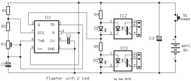
The circuit is based on the IC1 that is 555, for the creation of alternate flashes from the two led D1-2, that can be also different colour. The frequency of alternation can be regulated from the trimmer R3 and...