
Servo motor Tester with PIC12F675
The described servo tester is a compact electronic device designed to evaluate the functionality of various modern servos. The core of the circuit is based on the PIC12F675 microcontroller, which is responsible for generating the control signals necessary for servo operation. This microcontroller features an internal timer that provides a precise timing mechanism, allowing for consistent frame durations of 20 milliseconds, which is the standard for most servos.
The circuit includes two pushbuttons: CENTRE and SWEEP. The CENTRE button allows the user to position the servo at its neutral point. When this button is pressed, the microcontroller interprets the command and sends a signal to the servo to move to its center position. The user can then adjust the potentiometer (R5, a 5K variable resistor) to fine-tune the servo's position within a specific range.
The SWEEP button activates a sweeping function, which causes the servo to move back and forth across its entire range of motion. The rate at which this sweeping occurs is adjustable via the potentiometer, allowing the user to set the speed of the motion according to their requirements. This feature is particularly useful for testing the responsiveness and range of motion of the servo.
The circuit design incorporates various passive components to ensure stable operation. Resistors R1 (1K), R2 (10K), R3 (82R), and R4 (10K) are used for biasing and signal conditioning. Capacitors C1 (27pF), C2 (27pF), and C3 (100nF) are employed for decoupling and filtering purposes, ensuring that the microcontroller operates reliably without interference from noise.
A 4.7V zener diode (D1) is included in the design to provide voltage regulation, protecting the circuit from voltage spikes and ensuring stable operation. The 10MHz crystal (Q1) is utilized to provide a precise clock signal for the microcontroller, which is essential for accurate timing and operation of the servo control signals.
This servo tester serves as an essential tool for hobbyists and engineers alike, allowing for comprehensive testing and calibration of servos in various applications. Its simple yet effective design makes it accessible for users with varying levels of experience in electronics.This is a simple servo tester which will comprehensively test the capabilities of almost any modern servo. It has two pushbuttons, CENTRE and SWEEP and a potentiometer which works as follows: CENTRE Does exactly that, centers the servo, afterwards the potentiometer determines position.
SWEEP Sweeps the servo back and forth at a rate determined by the potentiometer setting. The PIC uses its internal timer to set up a constant frame duration of 20ms and the on/off ratio is set by the user. Parts List R1 = 1K R2 = 10K R3 = 82R R4 = 10K R5 = 5K potentiometer C1 = 27pF C2 = 27pF C3 = 100nF D1 = 4,7V zener diode Q1 = 10MHz crytal IC1 = PIC12F675 🔗 External reference
Related Circuits
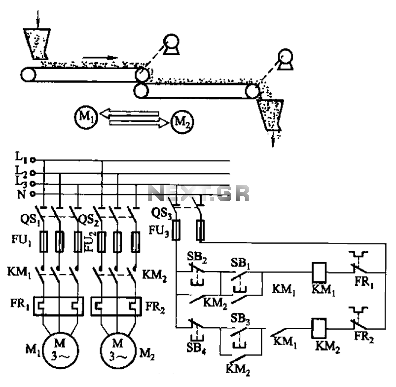
The circuit depicted in Figure 3-86 utilizes a line utilization time relay to control two motors, starting one before the other after an initial stall. The time relay KTi can be adjusted to modify the starting interval of the...
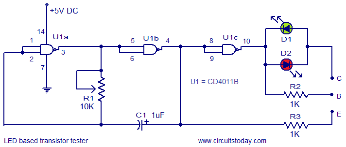
This circuit represents a simple transistor tester that utilizes two LEDs to indicate the condition of a transistor. It is capable of testing both PNP and NPN transistors. The core component of the circuit is the quad 2-input CMOS...
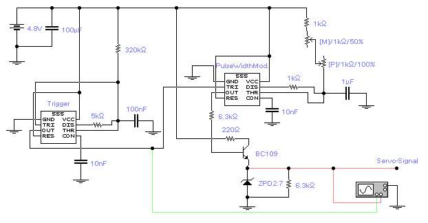
The first timer IC555 generates a negative trigger signal with a frequency of approximately 45Hz, producing a trigger impulse every 22ms. It is important not to exceed 50Hz for optimal servo performance. The second timer IC555 produces a modulated...
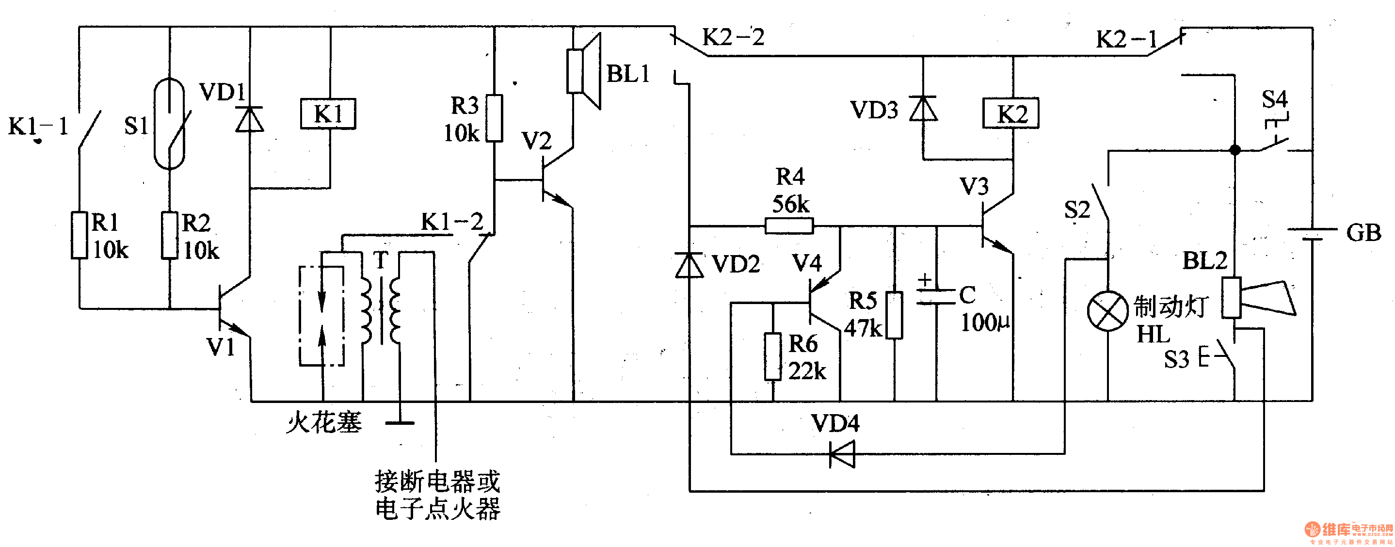
The circuit comprises a trigger circuit, an alarm control circuit, and a reset circuit for the alarm. The trigger circuit includes mercury switches (S1), a resistor, transistors (V1), and a relay (K1). The alarm control circuit is made up...
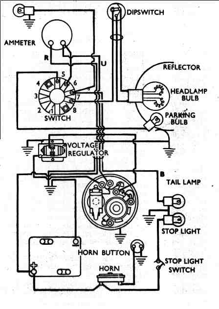
This diagram illustrates a redundant closed-loop ground wiring system designed to minimize reliance on the frame for grounding in the charging circuit. The second diagram depicts the configuration of a bike utilizing a 12-volt Alton generator along with an...

The circuit operates with relevant components highlighted in the manual's draw mode. Figure A presents a circuit schematic, while Figure B illustrates a typical conventional secondary circuit layout. Figure E showcases an improved secondary circuit schematic diagram that incorporates...
Warning: include(partials/cookie-banner.php): Failed to open stream: Permission denied in /var/www/html/nextgr/view-circuit.php on line 713
Warning: include(): Failed opening 'partials/cookie-banner.php' for inclusion (include_path='.:/usr/share/php') in /var/www/html/nextgr/view-circuit.php on line 713