
Shutter tester
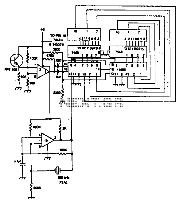
The shutter speed tester functions as a precision instrument for measuring the duration of exposure in photographic equipment. It utilizes a crystal oscillator to produce a stable frequency output, which is essential for accurate timing measurements. The frequency counter is employed to tally the pulses generated by the oscillator during the time the shutter is open, providing a direct correlation to the shutter speed.
The photo-transistor-operated gate generator plays a crucial role in this system by detecting the opening of the shutter. When the shutter opens, the photo-transistor is activated, allowing the oscillator's pulses to pass through to the frequency counter. This process ensures that only the pulses corresponding to the open shutter duration are counted, leading to an accurate measurement of the shutter speed.
An important feature of this design is the automatic reset mechanism. As soon as the shutter opens, the system resets itself to prepare for the next measurement cycle. This automation enhances the efficiency of the tester, allowing for quick successive measurements without manual intervention.
In summary, the shutter speed tester is a sophisticated device that combines multiple electronic components to provide precise shutter speed measurements, making it an invaluable tool for photographers and technicians aiming to optimize camera performance.Shutter speed tester combines frequency counter, crystal oscillator, and photo-transistor-operated gate generator. Oscillator pulses are counted as long as the shutter is open Reset is automatic at the instant the shutter opens. 🔗 External reference
Related Circuits
As I was developing my IR Extender Circuit, I needed to find a way of measuring the relative intensities of different Infra red light sources. This circuit is the result of my research. I have used a photodiode, SFH2030...
This circuit is essential for quickly determining the functionality of various remote control transmitting infrared (IR) lights. It is powered by a battery and constructed from a few commonly available and inexpensive components, fitting into a compact enclosure. The...
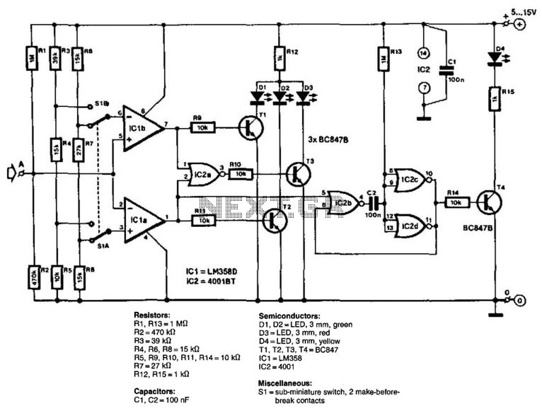
The circuit consists of two comparators that operate with different reference voltages supplied by separate potential dividers. Divider R3/R4/R5 provides a voltage of approximately 40% of the supply voltage (Ucc) to pin 6 of IC1B and about 16% of...
Liquid crystal displays (LCDs) are available in various versions and sizes. The wide variety of features has led to some confusion regarding pin configurations. Consequently, even after extensive searching for a suitable screen, users often encounter difficulties in utilizing...
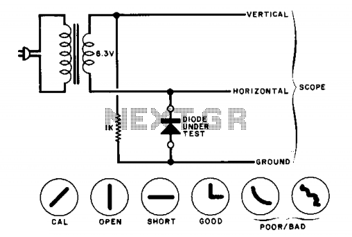
The circuit will display curves on an oscilloscope, depending on the state of the diode. To calibrate, replace the diode with a 1000-ohm resistor and adjust the oscilloscope gains for a 45-degree line. The drawings illustrate some expected results. The...
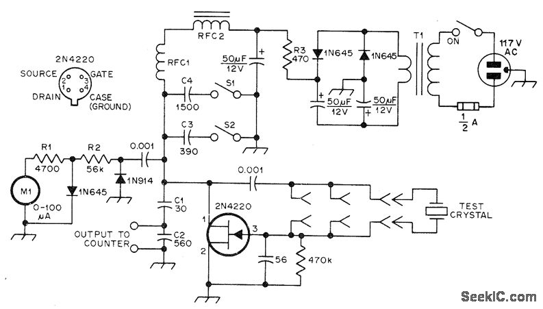
The JFET Pierce oscillator is designed to test any crystal within a frequency range of 50 kHz to 25 MHz, accommodating the upper frequency limit of fundamental-mode crystals without the need for tuning. It is capable of driving a...