
signal tracer and injector

The test circuit for audio and radio equipment is an essential tool for engineers and technicians in the field of electronics. The circuit's dual functionality allows for both signal injection and audio tracing, providing versatility in diagnosing faults. In injection mode, the circuit generates a square wave signal that is rich in harmonics, which is particularly effective for testing the frequency response of audio equipment and radio receivers.
The single pole double throw switch is a critical component, enabling seamless transitions between the two modes. In trace mode, the connection to the collector of the last transistor allows for the monitoring of audio signals through headphones, enabling the user to listen to the output directly. The use of emitter follower configuration for the transistors ensures that the circuit maintains a high input impedance, minimizing loading effects on the device under test while providing high gain.
DC blocking is implemented using a 1nF capacitor at the probe end, which prevents any DC offset from affecting the audio signal being traced. The capacitive coupling between the two stages ensures that only the AC components of the signal are passed through, which is critical for accurate audio signal analysis.
When the switch is toggled to the position indicated by the blue dot, the circuit transforms into an astable multivibrator. In this configuration, both transistors generate a continuous square wave output. The frequency of this output can be adjusted by varying the component values associated with the timing of the astable circuit, allowing for a wide range of frequencies to be tested, from audio frequencies up to several hundred kilohertz. This frequency range is particularly useful for testing AM radio receivers, as it allows for the injection of signals that can be easily demodulated by the receiver circuitry.
Overall, this simple yet effective test circuit is a valuable asset for troubleshooting and maintaining audio and radio equipment, providing both signal injection capabilities and audio tracing functionality in a compact design.A simple test circuit to fault find audio and radio equipment. Can be used to inject a square wave signal, rich in harmonics, or used with headphones as an audio tracer. A single pole double throw sitch is used to switch between inject and trace modes. The diagram is drawn in trace mode, the earpiece being connected to the collector of thelast tra nsistor. Both transistors are wired as emitter followers, providing high gain. DC blocking is provided by the 1n capacitor at the probe end, and the two stages are capacitively coupled. when the switch is thrown the opposite way (to the blue dot) both transistors are wired as an astable square wave generator.
This provides enough harmonics from audio up to several hundred kilohertz and is useful for testing AM radio Receivers. 🔗 External reference
Related Circuits

The multi-purpose signal generator circuit consists of integrated circuit oscillators and frequency dividers. It generates square waves ranging from high frequencies to sub-audio frequencies and also produces a frequency standard in the VHF range. The alternative oscillator section feeds...
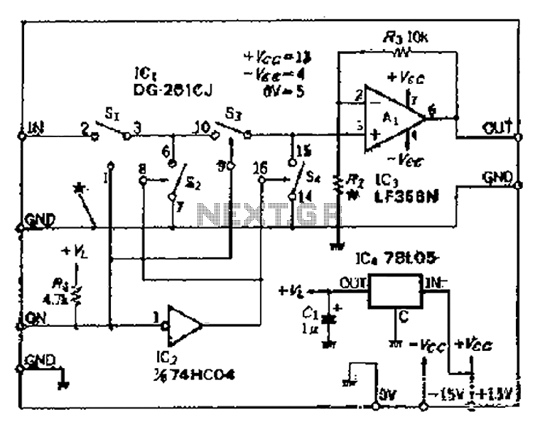
Analog switches SL and SA disconnect the inverted logic signal to terminal 2. S1 and S4 are turned on, allowing capacitance between S1 and S8 to couple. S2 and S4 shunt with an on-state resistance ranging from 50 to...
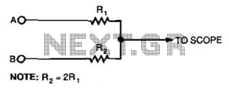
This simple resistor circuit can be used to trick an oscilloscope into displaying two logic signals on one channel. By selecting R2 to be twice the value of R, the oscilloscope trace will show one of four distinct analog...
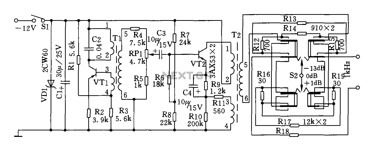
This circuit can generate a signal of 1 kHz and offers three output level options. It is suitable for testing communication equipment maintenance and barriers, providing a quick and accurate method to identify points of failure in televisions, stereos,...
An inverting mode amplifier is required for precision accelerometers due to their typical charge output characteristics. This amplifier is utilized to convert charge into voltage. An inverting mode amplifier is a critical component in applications involving precision accelerometers, which often...

This UHF wideband signal amplifier provides a total gain of 10 to 15 dB within the 400 - 850 MHz frequency range, making it suitable for applications where the television signal is weak. For optimal performance, the component pins...