
Sim card to PC adapter cable
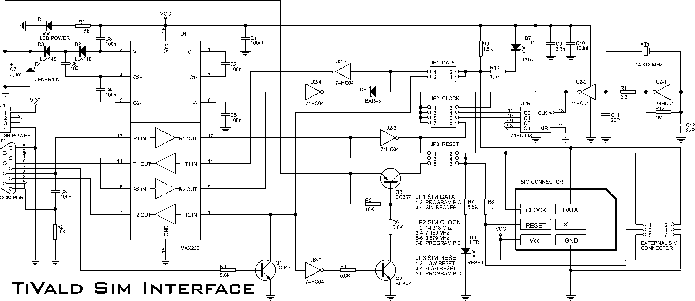
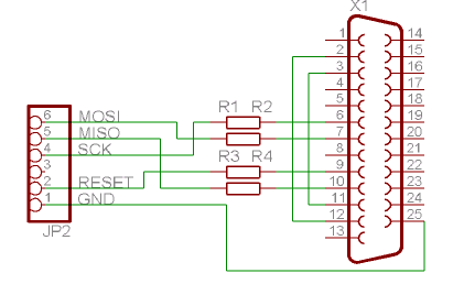
The electronic adapter is designed to interface with smartcard readers, providing flexibility in power supply options and ensuring robust communication. It can be powered from the smartcard reader's VCC line, which simplifies the setup, or an external 5 V source can be employed if a more stable supply is required. The integration of the MAX232 device is critical for converting TTL logic levels to RS-232 standards, which is essential for reliable communication between the smartcard reader and the connected devices.
The connection of the RST line to the MAX232 allows for effective error handling and resynchronization. In scenarios where protocol errors occur, this setup ensures that the communication can be reestablished without manual intervention, thus enhancing the system's reliability. Testing the circuit with a terminal emulator is straightforward; by turning off local echo, the user can verify that the interface is operational based on the immediate display of typed characters.
Moreover, the adapter circuit serves a dual purpose by enabling a PC to monitor the data exchange between the smartcard reader and an actual smartcard. This feature is particularly useful for debugging and development purposes, as it allows for observation of the communication protocol in real-time. The requirement to connect the real card and the adapter in parallel to the reader ensures that the data flow remains intact while preventing any interference from the PC software. This capability makes the adapter a versatile tool in the field of smartcard technology and electronic communication.The adapter electronic gets its power supply from the smartcard reader device VCC line or you can use an external 5 V supply if you wish. The card slot"s RST line is connected using one of the TTL->RS-232 drivers in the MAX232 to DCD, so that the software and the reader can easily resynchronize in case of a protocol error.
You can test the circuit with a terminal emulator and external +5 V supply by switching of local echo if you still see every typed character immediately on the screen, the interface should be all right. You can also use this adapter circuit to allow a PC to listen to the data traffic between a reader and a real card.
Just connect the real card and the adapter parallel to the reader and don"t let the PC software transmit anything. 🔗 External reference
Related Circuits
National Instruments Multisim now features microcontroller unit co-simulation capabilities, enabling the inclusion of a microcontroller, programmed in assembly or C code, within SPICE-modeled circuits. The MCU functionality in Multisim allows students, educators, and professional users to program MCUs in...

This is a car alarm simulator that uses an LED as a simulation output. This simple circuit can indicate whether a car is running or not by detecting the voltage difference when the car is on and off. This...
Two complementary transistors create a basic oscillator with a frequency range of approximately 0.5 to several Hz. This circuit serves as a metronome, timer, or pacer for exercise equipment. The oscillator circuit utilizes a pair of complementary transistors, typically one...
This tester can be used to check the polarity of any power source, and is therefore very useful when installing automotive equipment, alarm systems or anything else you can think of. Because this circuit is so simple and cheap,...
The Atmega 128 is similar to other AVR microcontrollers. It is in-system programmable (ISP). An earlier article discussed the AVR ISP programmer, which utilizes a 74HC244 buffer for safety when programming the AVR. However, if a programmer for the...
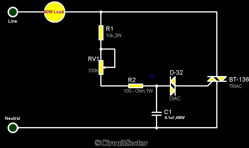
The circuit diagram presented is a triac-diac electronic fan regulator designed to reduce power consumption of electric fans, even at low speeds. Traditional resistor-inductor fan regulators tend to generate excess heat, wasting energy when the fan operates at lower...