
Simple Moisture Detector

This circuit serves as a moisture detection system, utilizing a pair of probes to monitor moisture levels in soil or other materials. When moisture is detected, the flip-flop configuration (IC1a and IC1b) plays a crucial role by storing the state of the moisture detection. The output from the flip-flop controls the tone oscillator (IC1c), which generates an audible tone through the buzzer. The inclusion of capacitors C1 and C2 ensures that the circuit initializes correctly upon power-up, providing a reset function that can also be manually triggered via switch S1.
The option to replace the passive buzzer with a relay expands the circuit's application to higher power devices, such as lamps or sounders, which require more current than a buzzer can provide. The relay's coil voltage rating must be carefully selected to ensure compatibility with the circuit's supply voltage, particularly noting that a 6-volt relay is suitable for a 9-volt supply. This design consideration is essential to prevent damage to the relay and ensure reliable operation.
In terms of power consumption, the circuit's standby current is efficient, allowing it to be powered for extended periods without significant battery drain. However, when the relay is activated, the current draw increases, highlighting the importance of selecting an appropriate power source that can handle the peak current requirements.
The flexibility of the supply voltage range allows for versatility in various applications, although caution is advised when operating below 8 V, as this may limit the functionality of the relay. Additionally, the sensitivity of the moisture detection can be adjusted by modifying the resistor R2, providing a means to fine-tune the circuit's response to varying moisture levels. This feature is particularly beneficial in environments with fluctuating moisture conditions, ensuring optimal performance of the detection system.The function of this circuit is to sound a buzzer, or, optionally, actuate a relay, when a certain moisture level is detected between a pair of probes. The circuit has a memory` in the form of a flip-flop, IC1a-IC1b, which enables or disables a tone oscillator, IC1c.
The flip-flop is reset either by C1 and C2 when the supply voltage appears, or by push-button S1. This may not reset the alarm, however, which will sound again until the probes are dry`. The (passive) buzzer may be replaced by a relay actuating an externally connected sounder, lamp or other high-power signalling device. Because the duty factor of the coil voltage is about 0. 5, the relay should be a type with a coil voltage which is lower than the supply voltage. A 6-volt type is suggested if the circuit is powered from a 9-volt supply. The circuit has a modest standby current consumption of between 4 and 5 mA. This rises to about 40 mA when the relay is actuated. The supply voltage is uncritical and may be anything between 3 V and 15 V. Note, however, that it may not be possible to use a relay if a supply voltage lower than about 8 V is employed.
If the circuit is found to be too sensitive, the value of resistor R2 may be decreased. 🔗 External reference
Related Circuits
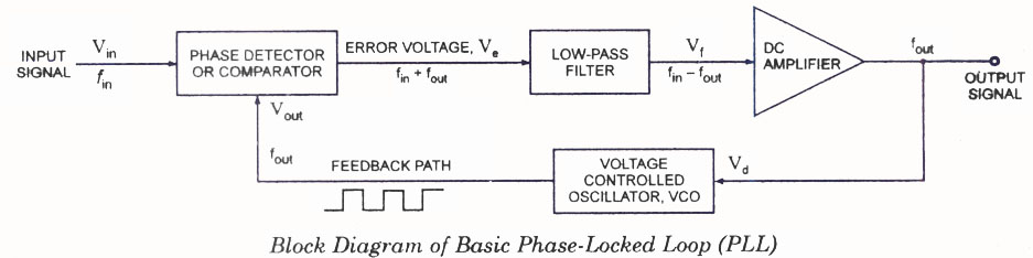
The operating principle of a Phase Locked Loop (PLL) is illustrated with a block diagram that includes a Phase Detector, Voltage Controlled Oscillator, and Low Pass Filter. A Phase Locked Loop (PLL) is an essential electronic circuit used in various...
Wind 6 turns of solid wire on a pen or pencil that is just under 1/2 inch in diameter. Remove the wire from the pencil and spread the winding to make a length of 3/4 inch. Solder C2 somewhere...

This lie detector circuit diagram provides two readings: one for challenging questions directed at the subject and another to display the subject's emotional state in general. The emotional states are detected not only by heart rate variations and perspiration...

This simple AVR programmer is capable of transferring hex programs to most Atmel AVR microcontrollers. It is more reliable than many other basic AVR programmers available and can be assembled in a short amount of time. This programmer supports...
The Accu charger circuit is straightforward and simple to construct, requiring no more than ten components. In addition to its ease of assembly, this charger circuit is also cost-effective and highly efficient. The circuit requires a power supply from...

Microchip's PIC18F14K50 is an excellent choice, offering a wide range of features in a compact package at an affordable price. While focusing on the chip's numerous capabilities, a specific requirement for its flash programming was overlooked during the design...