
Simple Oscillator / Pipe Locator

The described oscillator circuit typically consists of a resistor, a capacitor, and a single transistor. The operation of this circuit relies on the charging and discharging of the capacitor through the resistor, which in turn controls the base current of the transistor. As the capacitor charges, the voltage across it increases until it reaches a threshold that turns the transistor on. This action allows current to flow from the collector to the emitter, effectively discharging the capacitor and causing the cycle to repeat.
In a practical implementation, the values of the resistor and capacitor can be adjusted to set the frequency of oscillation. For example, using a larger capacitor or resistor will result in a lower frequency, while smaller values will increase the frequency. This type of oscillator is often used in applications such as clock generation for digital circuits, tone generation in audio applications, or as a simple signal generator for testing purposes.
The simplicity of the circuit makes it an excellent choice for educational purposes, allowing individuals to understand the fundamental principles of oscillation and circuit design. Furthermore, this basic oscillator can serve as a building block for more complex circuits, demonstrating the versatility and importance of oscillators in electronic systems.Sometimes the need arises to construct a really simple oscillator. This could hardly be simpler than the circuit shown here, which uses just three compone.. 🔗 External reference
Related Circuits
The hysteresis characteristic indicates that the voltage level transitions to high (H) when the input voltage of the inverter rises from 0 V, and the voltage level transitions to low (L) when the input voltage descends from +5 V....
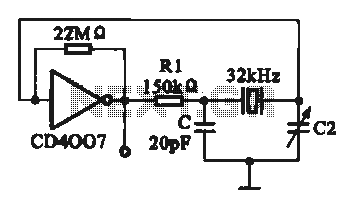
A 32 kHz clock oscillator is essential for digital circuits, as depicted in the schematic. The 32 kHz crystal clock oscillator serves to provide a time reference signal for the digital circuit. It utilizes a CMOS integrated circuit, specifically...
This simple door chime protects the door and emits a loud alarm tone in the event of a theft attempt. The circuit is straightforward and battery-operated. A Normally Closed (NC) reed switch and magnet are utilized to trigger the...
Three examples of Wien Bridge oscillators are shown below. The first uses three bipolar transistors. The second uses a bipolar and JFET, and the third is the more popular type using an op-amp for minimal parts. The idea is...
A compact 325mW amplifier with a voltage gain of 200, suitable for use as a bench amplifier, signal tracer, or to amplify the output from personal radios. The circuit utilizes the National Semiconductor LM386 amplifier. In the schematic, the...
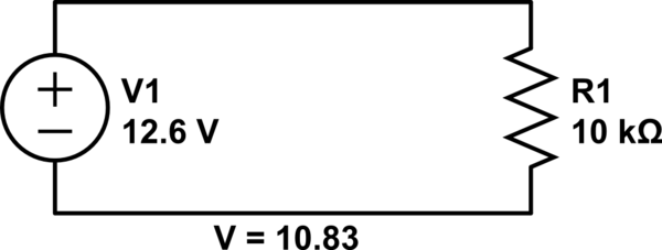
Connect a 12V fan to this circuit that consumes 70mA (0.07A), ensuring the circuit can supply at least that amount of current. There appears to be a misunderstanding regarding the analysis. The voltage drop across the resistor equals the...