
Mini-Z Track Timer Ex
The display employs multiplexing, consisting of 32 digits, each comprising 7 segments plus a decimal point, resulting in a total of 256 LEDs to control. This multiplexing utilizes 5 I/O pins for digit selection and 8 I/O pins for segment selection. The 5 digit select lines are demultiplexed using two 74LS154 (not HC as indicated in the schematic) 4-Line to 16-Line Decoder/Demultiplexers. The chip select function is managed by the fifth bit and transistor Q40. The microcontroller software governs the display, selecting a new digit and illuminating the corresponding segments during each update cycle. The segment display is controlled within the main software loop, while timing and button press functionalities are handled through interrupt routines. A 74LS139 1 of 4 Decoder/Demultiplexer is also employed to indicate the operating mode lights, which signify whether the unit is in Practice, Qualifying, Race, or Setup modes.
The project is divided into two schematics: the controller and the display, reflecting the fabrication process, which involved two separate boards connected via a 34-pin IDC connector and cable. A snippet of the display schematic illustrates the multiplexing mechanism, which selects the digit (Digit1-32) to be displayed and the segments (SELSEGA-F) to be illuminated. The entire assembly was constructed using breadboards, a choice influenced by the daunting size of the required PCB. The wiring of the displays proved to be a labor-intensive task. Sourcing the 7-segment LED displays was challenging; initial attempts yielded uneven brightness from components acquired at Jaycar. Subsequent purchases from Dick Smith provided high-intensity displays with consistent brightness, although local stock was limited, necessitating visits to multiple stores to obtain the required 32 displays. In hindsight, ordering components online would have been more efficient, a method that has since become viable with the advent of reliable suppliers like Digikey and Mouser, along with local options such as Rockby and RS Components.
The segment select transistors are positioned on the left side of the board, concealed beneath cardboard. The display select transistors and resistors are situated under each display, also hidden from view. The decoder/demultiplexers are located at the bottom of the assembly, while the chip select transistor is discreetly placed to maintain a clean layout.TrackTimer1 was a simple project - a bit of electronics in the car detectors, a simple Parallel Port interface to the PC, and a bit of software to provide an F1 style display. I`m pretending the motivation for TrackTimer2 was a lap counter that could be used outside, but I really just wanted something else to work on, and I wanted to try a project
using microcontrollers. Here`s an action shot of TrackTimerEx, showing Car 1 has completed 3 laps, with best lap time and last lap time. I think this shot was taken while still developing it because the sides of the box have not been placed.
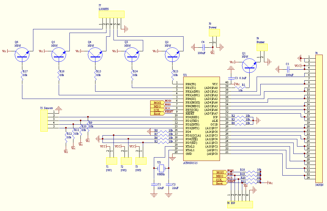
TrackTimerEx has the same functionality as TrackTimer, except that it is a standalone, portable unit. Also, it can only display numbers, and some pseudo words made up from the 7 Segment LED displays. It only has a buzzer so its sound is limited. The circuit is based around the Atmel AT90S8515. All but 1 of the I/O pins have been used: 15 for the display multiplexing, 1 for the buzzer, 3 for the input switches, 4 for the track lap sensors, 5 for the gantry lights.
4 are dedicated to the ISP programming which could have also been used for other purposes. As already mentioned, the display is multiplexed. There are a total of 32 display digits, each made of 7 segments and 1 decimal place. Hence there are 8x32, or 256 LEDs to control. The multiplexing is done by using 5 I/O pins to select the digit, and 8 I/O pins to select the segments. The 5 digit select lines are demultiplexed using 2, 74LS154 (not HC as shown in the schematic), 4-Line to 16-Line Decoder/Demultiplexer.
The chip select function is contolled by the 5th bit, and transistor Q40. The display is controlled by the microcontroller software. Each update cycle, a new digit is selected and the appropriate segments are lit. The displaying of the segments is controlled in the main loop of the software. All other functionality - timing, button presses - is controlled in the interrupt routines. A 74LS139, 1 of 4 Decoder/Demultiplexer, is also used to display the mode lights. These are used to display whether the unit is running in Practice, Qualifying, Race, or Setup modes. The project is broken up into 2 schematics: the controller and the display. This is also how it was fabricated, split into 2 boards, connected by a 34 pin IDC connector and cable. Here`s a snippet of the schematic for the display. The multiplexing works by selecting which digit, Digit1-32, is going to be displayed, and which segments are going to be lit, SELSEGA-F.
For some silly reason, I decided that I would make the whole thing using bread boards. I think I was intimidated by the size of the PCB I`d have to make. I didn`t realise the chore it would be to wire up all of the displays. The 7 segment LED displays were damn near impossible to source. I grabbed a couple from Jaycar, and their brightness was uneven. Then I tried Dick Smith. They had high intensity ones that had a consistent high brightness. The only problem was that each store around me only had a few each. The sales guy said he could order them in from other stores, but I`d have to pay the courier costs. Yeah right. So I drove around to about 7 stores to find the 32 displays. Next time, I`ll just order them over the internet, which was not something that was really viable back when I did this - either outrageously expensive - cost, delivery, import duties - or they didn`t ship internationally. Thankfully this is not an issue anymore, as I regularly get stuff from Digikey, and Mouser, and there are a couple of locals, Rockby, and the expensive RS Components (but they do have a big range).
The segment select transistors were placed on the left hand side of the board (from the front), hidden under the cardboard. The display select transistors and resistors are under each display, also hidden by the cardboard. The decoder/demultiplexers are at the bottom. The chip select transistor was stealthily hidden 🔗 External reference
Related Circuits
The schematic presented originates from buildcircuit.com. This circuit functions as a music generator, infrared transmitter, and LED blinker, depending on the values of R1, R2, and C1. A minor modification to the previous circuit allows it to operate as...
This device is a combination digital clock timer and solar panel charge controller designed to maintain a deep cycle battery charged by a solar panel. The timer output controls a 12-volt load for a 32-minute interval each day. The...
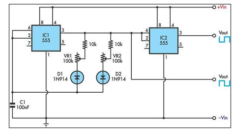
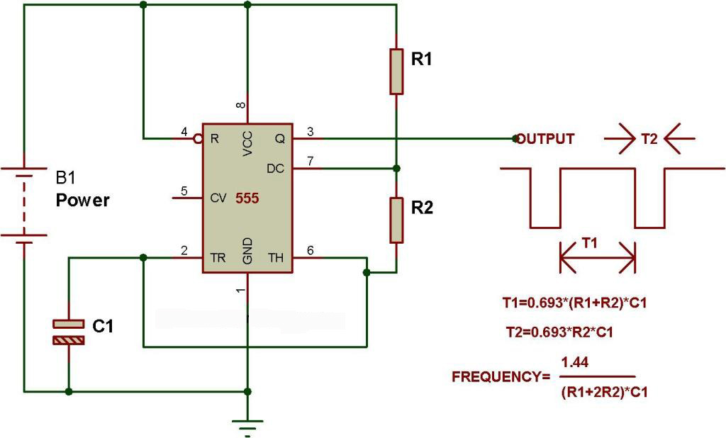
This circuit allows for the independent variation of the on/off times of a 555 timer across a wide range. This capability is not achievable with a conventional 555 timer circuit. The described circuit enhances the functionality of the standard 555...
The crime prevention bell device produced approximately 20 years ago remains in active service. It has effectively deterred thieves on multiple occasions by triggering an alarm as they attempt to enter. The bell continues to ring, functioning as a...
A switched timer for intervals of 5 to 30 minutes incremented in 5 minute steps. Simple to build, simple to make, nothing too complicated here. However, you must use the CMOS type 555 timer designated the 7555; a normal...
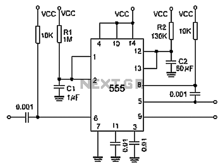
A 0.001 F coupling capacitor connects the output of the first half of a 556 timer to the input of the second half, providing an individual delay that equals the total delay. The 6-foot ground can immediately activate the...