
Single Chip FM Transmitter For Short Range Application

The FM transmitter circuit is designed to function within the frequency range of 88 to 108 MHz, which is the standard FM broadcast band. This circuit is capable of transmitting audio signals, making it suitable for applications such as personal radio broadcasts, remote audio streaming, or educational purposes.
The core components of the FM transmitter include an audio input stage, an oscillator, a modulator, and an output stage. The audio input stage typically consists of a microphone or line-level audio source that converts sound waves into electrical signals. These signals are then fed into the oscillator, which generates a carrier wave at a specific frequency within the FM band.
The modulator is responsible for varying the frequency of the carrier wave in accordance with the input audio signals, effectively encoding the audio information onto the carrier wave. This modulation allows the audio signals to be transmitted over the airwaves.
The output stage amplifies the modulated signal to ensure it has sufficient power to be transmitted over longer distances. The output power can be adjusted based on the design of the circuit, which may involve the use of transistors or integrated circuits to achieve the desired amplification.
Additionally, the circuit may include components such as filters to reduce unwanted harmonics and improve signal quality, as well as an antenna for effective radiation of the transmitted signal. The choice of antenna type and its design is critical for optimizing transmission range and clarity.
Overall, this FM transmitter circuit serves as a versatile tool for audio broadcasting, enabling users to share audio content wirelessly within a designated area. Proper tuning and setup are essential to ensure compliance with local regulations regarding radio frequency transmission.The FM transmitter circuit here works in the broadcast band 88 to 108MHz, and can be used to broadcast audio signals for remote listening. The output power.. 🔗 External reference
Related Circuits

The typical application circuit for the TDA1514A includes resistors R2 and R3, which form a feedback circuit to adjust their ratio, thereby creating an adjustable circuit loop gain. To enhance the dynamic range of the circuit, capacitors C5 and...

The 1B32 application circuit features multiple pressure sensors as illustrated in the figure. Excitation power is supplied through the AD542, which is followed by a TIP32 transistor that drives multiple bridge sensors. The AD542 operates as a Bi-FET in...

This project is an application that utilizes the W5100 library for network connections, the DS1307 for time display, and the MAX7219 for controlling 7-segment displays. It features a web page that allows users to read the time and modify...

A simple FM transmitter circuit can be designed using the MC2833 integrated circuit, which is intended for cordless telephones and FM communication equipment. It features a microphone amplifier, a voltage-controlled oscillator, and two auxiliary transistors. The final output frequency...
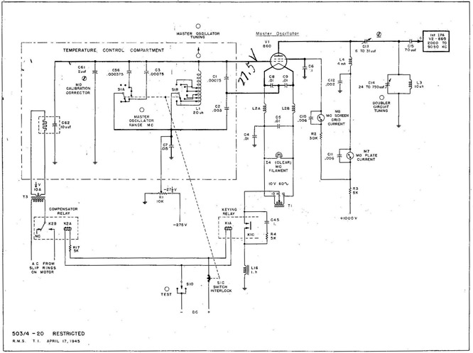
With the equipment ready for operation, the main line switch (S-831), the emergency switch (S-12), and the main line contactor contacts (K-831B) are all closed. The keying relay main contacts (K-1C) ground the center tap of the MO filament...
An FM modulator that modulates a carrier frequency with the composite signal, and an RF amplifier that provides enough power to be transmitted through an antenna. Here is the schematic diagram of the FM transmitter circuit: The core of...