
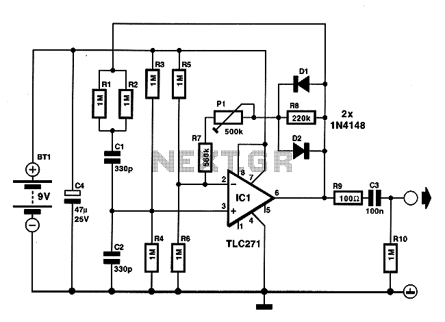
sound generator
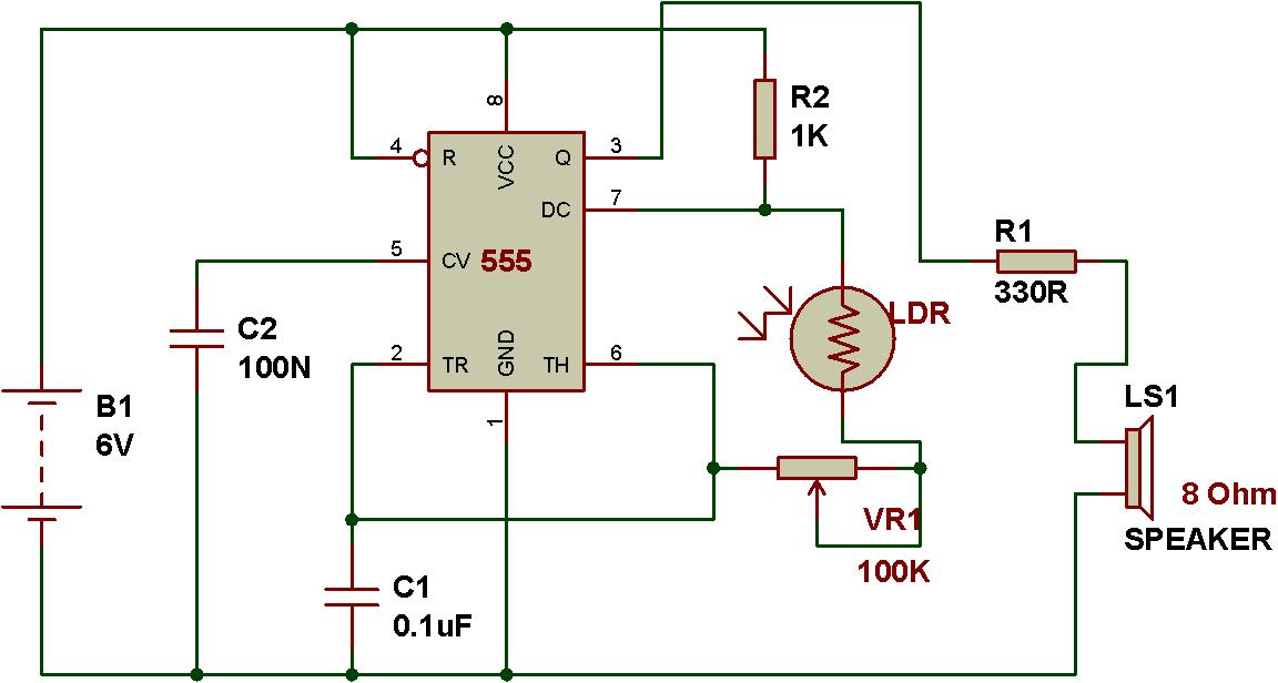
The described circuit leverages the 555 timer in astable mode to create a versatile sound generator. In this configuration, the 555 timer continuously switches between its high and low states, generating a square wave output. The frequency of this output is determined by the resistances connected to pins 6 and 7, as well as the capacitor connected to pin 2. By replacing the fixed resistor with an LDR, the circuit becomes responsive to ambient light levels. The LDR's resistance decreases as light intensity increases, leading to a higher frequency output, while a decrease in light results in a lower frequency output.
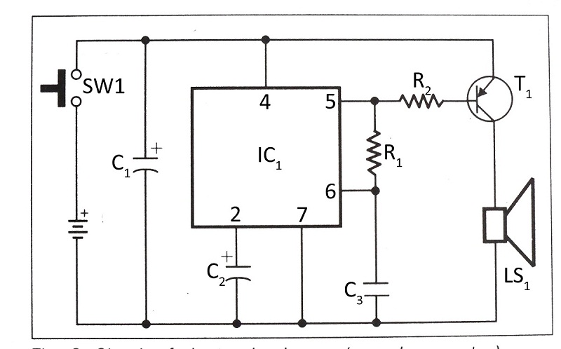
In this design, the toy organ functionality is achieved by integrating multiple switches that serve as keys. Each switch, when pressed, modifies the resistance across the 555 timer's threshold and trigger pins, thus altering the frequency of the output sound. The sound produced can be further shaped by adjusting the capacitor value, which, in conjunction with the LDR, allows for a range of audible tones.
The application of this circuit extends beyond educational purposes; it can be a foundational project for understanding the principles of sound synthesis, resistance variation, and the functionality of the 555 timer in various configurations. The use of an LDR not only enhances the learning experience by demonstrating real-time interaction with light but also provides a hands-on approach to exploring the relationship between resistance and frequency in electronic circuits.Circuit given below is configured on astable mode of operation. In place of a fixed resistance, LDR has been kept for getting variable resistance for the 555 timer to work in astable mode. Now, as the resistance increases or decreases in accordance to the light falling on LDR, we hear sound of different frequencies.
The logic of sound generator u sing 555 can be used to make a simple toy organ. As we press different keys (Push to ON switch), the resistance between pin 6 and pin 7 varies and that produces sound of different frequencies. Here, you can see that the logic of a blinker has been used to make a sound generator. Use of LDR makes us easier to understand that the sound frequency varies according to the resistance variation in LDR.
We can make a simple toy organ using the logic of sound generator. As we press different switches, the output frequency of the circuit varies and it produces sounds of different frequencies. 🔗 External reference
Related Circuits
Integrated circuit gates IC1-a and IC1-b form a monostable multivibrator, whose time constant is determined by capacitor C2 and resistor R3. When the transmitter is dekeyed and then almost immediately rekeyed, point TX+ goes low, causing pin 1 to...
The circuit utilizes an operational amplifier (IC1) configured in a non-inverting amplifier mode. Resistors R1 and R2 establish a gain of approximately 500. The variable resistor RV1 (sensitivity) adjusts the bias of the non-inverting input to the negative supply...
A friend requires a pulse generator oscillator circuit that maintains a stable frequency of 32.768 kHz for a digital CMOS binary counter. The pulse generator oscillator circuit designed to operate at a frequency of 32.768 kHz is commonly used in...
On occasions when it is necessary to determine if an amplifier is functioning, the most effective tool is an acoustic signal source with a frequency around 1 kHz. The specifications can be considered flexible, as rapid tests typically do...
This document presents a verified circuit diagram for a simple, interesting, and cost-effective electronic clapper (sound generator) circuit, along with a description of its functionality. The electronic clapper circuit is designed to activate sound generation through the detection of sound...
This DIY sound-activated lights circuit turns a lamp on for a brief duration when a dog barks or when a relatively loud sound is detected, creating the impression that the occupants are alerted. The condenser microphone is positioned to...