
speak spell

The integration of the Speak & Spell with low-cost computers represents a significant advancement in affordable technology solutions. The implementation of a simple interface allows for versatile applications, ranging from educational tools to security systems. The design effectively utilizes the existing hardware capabilities of the Speak & Spell, leveraging its speech synthesis features to enhance user interaction and accessibility.
The block diagram and schematic provide a clear representation of the system architecture and signal flow, ensuring that developers can replicate the setup efficiently. The use of PMOS technology in the Speak & Spell microprocessor highlights the importance of understanding device characteristics when designing interfacing circuits. The careful consideration of power requirements and the recommendation for a dual 22-contact card facilitate ease of assembly and compatibility with existing systems.
Overall, this approach not only demonstrates the potential for innovative applications in computing but also promotes the idea of cost-effective solutions in the realm of electronics, paving the way for further exploration and development in speech synthesis and interactive computing.A "talking" computer is not necessarily expensive - not if you mate one of the low-cost computers (Sinclair ZX-80, ZX-81, or Timex 1000) with Texas Instruments popularly priced "Speak & Spell" learning device. The combination give you several hundred clearly articulated words that expand the usefulness of the small computer.
All you need to make i t happen inexpensively is a simple interface and some software, all described here. Using these ideas, you might design a lowcost security/firealarm that vocalizes the nature of a problem ("Fire", "Theft", etc). You could also enhance your computer`s portability by making its output audible instead of displaying it on a video screen; write educational programs with truly meaningful student/teacher interaction; spice up computer video games with synthesized speech; create useful programs for the visually impaired; etc.
Here`s how it can be done. The Speak & Spell consists of a pushbutton keyboard, microprocessor, display, ROM (contains speech data), voice synthesizer, and loudspeaker. A block diagram of the system is shown in Fig. 1. The microprocessor communicates with the speech units through a 6-line bus with CNTL 1, 2, 4, and 8 forming a 4-bit data bus and PDC (processor data clock) and CS (chip select) forming a control bus.
The control commands used in the Speak & Spell are listed in Table I. The ROM contains the binary-coded speech data for synthesis of the spoken word. Each word has a specific starting address. When it is desired to output a particular word, the ROM address of the beginning of the word is sent to the voice synthesizer in five 4-bit nybbles, preceded by the LOAD ADDRESS (code 2) command. The data is then clocked into the voice synthesizer by the PDC signal. Once the 5-nybble word address is loaded, READ ROM (code 8) and SPEAK (code 10) commands are sent to cause speech to be generated.
If the BUSY SPEAKING (code 14) command is now sent, the voice synthesizer will raise the CNTL 1 line high until it finishes vocalizing. A schematic of the interface circuit between the computer and Speak & Spell is shown in Fig. 2. The microprocessor in the Speak & Spell uses PMOS devices that operate at -21 V. (A typical I/O line is shown within the processor. ) Because PMOS uses passive pulldown resistors, output current is limited. If ground potential is impressed on these lines, no harm will result, regardless of their state. The Z80A Parallel Input/Output (PlO) chip in the interface used for IC1 provides two bidirectional I/O ports: port A uses CMOS inverters (IC2) and open-collector pnp driver transistors (QI through Q6) as the outputs.
The emitters of these drivers are connected to the + 5-volt line, which is also connected to the positive (COM) of the Speak & Spell. Thus, when a transistor is conducting, the S&S MPU "sees" a logic 1 (0 V); when the transistor is off, the PMOS pulldown resistors bring the line to logic 0.
Port B of the PlO is used for input and receives its signal from R7 through R12, which limit the incoming signal from the Speak & Spell. In addition to interfacing with the Speak & Spell, with appropriate software, the PlO can propability for the computer, allowing use of joysticks and such functions as music, control, and process monitoring.
The circuit can be built on a dual 22-contact card similar to the Radio Shack No. 276-154. If you use the same edge-contact arrangement as in the coniputer, except for the clock line, the card is compatible with ZX bus expansion cards currently available. Use of sockets for the ICs and a miniature phone jack to interconnect the power supply are recommended.
The Speak & Spell draws about 200 mA and the interface about 70 mA at 5 V. If you are using a 16K RAM extension, the larger power supply can handle the extra load. Arrange switching so that both computer and interface power up at the same time. If you elect to use batteries in the Speak & Spell, discon 🔗 External reference
Related Circuits
If the offset value exceeds 5mV, adjust this value by experimenting with resistors, starting with 220K, connected from test point Z (the junction of R22 and R23) to +V if there is a negative voltage, or to -V if...
Occasionally, the output volume of an amplifier can be excessively high, leading to discomfort and potential damage to both the listener's ears and the loudspeaker. The circuit... Amplifiers are crucial components in audio systems, responsible for boosting audio signals to...
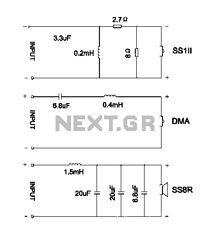
The divider acts as the speaker's brain and is crucial for sound quality. The music amplifier's output signal must be processed through a wave filter element to divide it into specific frequency signals for each unit. A scientifically and...
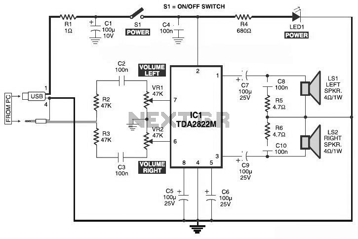
This is the circuit diagram of a USB-powered computer speaker, commonly known as multimedia speakers for PCs. The circuit features a single-chip design, operates on a low-voltage power supply, and is compatible with USB power from a computer. The USB-powered...
This circuit allows the use of an inexpensive loudspeaker as a microphone. Sound waves that reach the speaker cone cause fluctuations in the voice coil. The movement of the voice coil within the speaker's magnetic field generates a small...
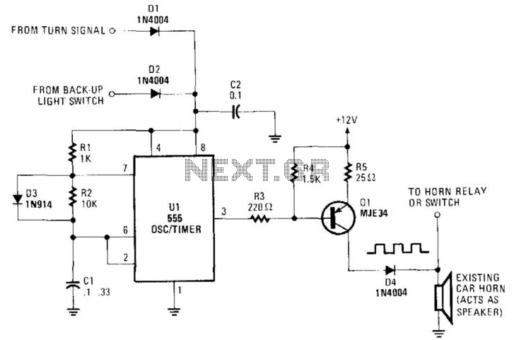
An auto horn operates as a speaker within a limited audio-frequency range. This circuit utilizes a 555 timer configured as an oscillator to drive an MJE34 transistor, which subsequently activates the horn. Normal horn operation is maintained through the...