
Speed Alarm For Cars
This circuit functions as a speed alert system by utilizing a combination of components to monitor vehicle speed and provide audio feedback without the need for visual displays. The LM2917 frequency-to-voltage converter serves as the central processing unit, converting frequency signals from the speed sensor into a proportional voltage. This voltage is compared against preset thresholds defined by the trimpots, allowing for fine-tuning of the speed limits.
Transistor Q1 acts as an amplifier, ensuring that the speed pulses are adequately processed before being sent to the LM2917. The RC networks serve to filter and smooth the signals, providing stable input to the comparators. The SCRs act as electronic switches that momentarily conduct when their respective thresholds are exceeded, providing a clear and immediate response to the driver.
The use of trimpots allows for customization of the speed thresholds, accommodating different driving conditions or personal preferences. By setting the thresholds slightly above the actual speed limits, the circuit minimizes false alerts while ensuring that the driver is informed if they exceed safe speeds.
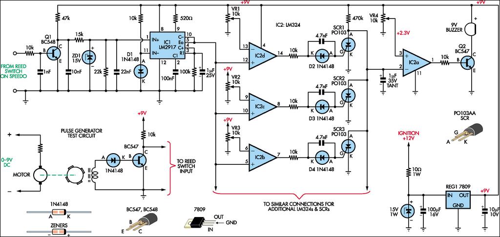
Overall, this circuit offers a practical solution to the challenges of speed monitoring in suburban driving, enhancing safety and convenience without the distractions of traditional speed displays.In normal suburban driving you pass through so many different speed zones that it can be a nuisance having to switch speed settings. The speed display can also be a distraction. This circuit eliminates the display and the need for speed selection. Each time you exceed a particular speed setting (eg, 40km/h, 50km/h, etc), a piezo buzzer will beep. Speed pulses are fed to the base of Q1 and the resulting waveform at its collector is fed via an RC network to the input of an LM2917 frequency-to-voltage converter, IC1. The resulting voltage is fed to three comparators (IC2d-IC2b) which have the reference voltages at their inverting inputs set by 10-turn trimpots VR1, VR2 & VR3.
The output of each comparator is applied via another RC network to the gate of an SCR. The anodes of the three SCRs are commoned connected to the inverting input of the remaining comparator, IC2a. Its non-inverting input is set to +2. 3V by trimpot VR4. In use, once you exceed the speed setting for a particular comparator, its associated SCR briefly conducts to pull pin 2 of IC2a low and a short beep is emitted by the piezo buzzer.
Then, as you exceed the next speed setting, another beep will be heard. The idea is make each speed setting a few km/h higher than actual so that if you are driving at the correct speed in a given zone, the buzzer will not sound. But as you increase speed, the buzzer will beep once as you exceed the speed setting for each zone. In this way, there is no need to continually switch speed settings as you drive through different zones and you can choose to ignore beeps that are not "illegal".
🔗 External reference
Related Circuits
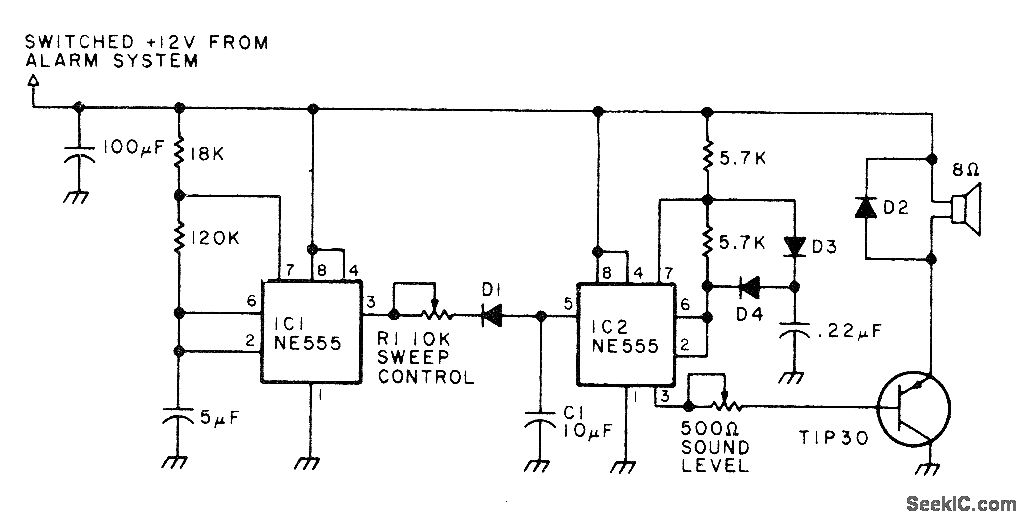
This circuit generates a high-intensity sound force field inside a vehicle, which is painful enough to deter a thief from entering the car after the alarm switch is triggered by opening the door. The circuit produces a square-wave output...
This infrared alarm barrier is designed to detect individuals passing through doorways, corridors, and small gates. The transmitter emits an invisible beam of infrared light. When this beam is interrupted by a person, a buzzer connected to the receiver...

A motion detection alarm circuit utilizing a PIR sensor for motion detection. When movement is detected by the PIR sensor, it triggers a delay circuit, Q1, and other components. The motion detection alarm circuit is designed to provide an alert...
When driving, it can be difficult to gauge the speed of a vehicle, particularly on straight highways. If the vehicle exceeds a safe speed, it may lead to accidents. Therefore, a Car Speed Alarm circuit is necessary to alert...
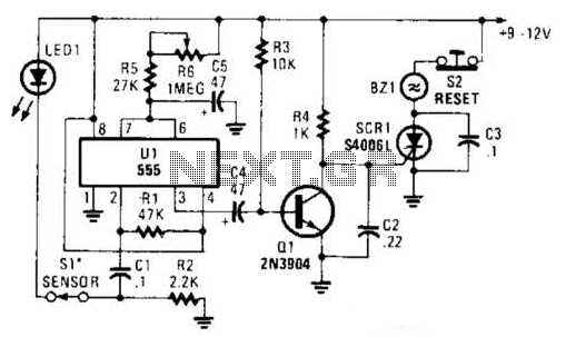
The alarm circuit utilizes a single 555 oscillator/timer (U1) that functions in both the alarm-trigger circuit and the entry-delay circuit. In this configuration, the trigger input of U1 at pin 2 is maintained in a high state through resistor...

The alarm can be utilized for various applications, including frost monitoring and room temperature monitoring. In its quiescent state, the circuit consumes only a few microamperes, allowing a 9 V dry battery (PP3, 6AM6, MN1604, 6LR61) to potentially last...