
square wave 2 sine wave convertion
To convert a TTL square wave into a sine wave effectively, a multi-stage approach is recommended. The initial step involves using a high-order low-pass filter to suppress the higher harmonics of the square wave. This could be achieved with a switched-capacitor Butterworth low-pass filter IC. The operation of this filter should be synchronized with a clock frequency that is 100 times greater than the desired cutoff frequency, which ensures that the filter can adequately smooth the square wave.
In cases where the input frequency varies, implementing a tracking filter is crucial. This filter's center frequency must dynamically adjust to match the input frequency, which can be accomplished using a phase-locked loop (PLL) configuration. The PLL can utilize a voltage-controlled oscillator (VCO) to generate the required clock signal, while a digital divider can produce the corresponding fundamental frequencies.
Following the initial filtering, the square wave should be passed through two integrators in series. The first integrator will transform the square wave into a triangular wave, which is a necessary step before converting it into a sine wave. The second integrator will then produce the sine wave output. However, it is essential to address the amplitude variation issue; as the frequency increases, the output amplitude decreases inversely with the square of the frequency.
To maintain a consistent output amplitude across the frequency range of 4Hz to 60Hz, an AGC circuit should be integrated into the design. This circuit will automatically adjust the gain based on the output signal level, ensuring that the amplitude remains stable despite variations in frequency.
The output from this configuration will provide a clean sine wave signal suitable for low-frequency applications. It is important to ensure that all components are appropriately rated for the frequency range and that the circuit is designed to minimize noise and distortion, thereby producing a high-quality sine wave output.I would like to convert a TTL square wave into sine wave. The frequency range of the square wave is: 4Hz-60Hz (yes its those evil low frequency experiments that I plant to take over the world with One approach is to filter the square wave with a high order filter. But if the frequency varies then you need a tracking filter whose center frequency v aries with the input frequency. That`s not trivial to do. Another technique is to run the square-wave through two integrators in series. The first integrator generates a triangular wave and the second generates a sine wave. The problem is that the output amplitude is inversely proportional to the square of the frequency so you need some sort of AGC circuit to maintain a constant amplitude. For a frequency range of 4Hz-60Hz the amplitude would vary by a factor of 225 or 47dB. A switched-capacitor Butterworth lowpass filter IC uses a clock that is 100 times the cutoff frequency.
The clock can be the VCO of a phase-locked-loop IC and a digital divider produces the fundamental frequencies. You need to clock them many times faster than the output frequency and you tell them the frequency digitally, so it is not a direct conversion, but that might help.
A switched-capacitor Butterworth lowpass filter IC uses a clock that is 100 times the cutoff frequency. The clock can be the VCO of a phase-locked-loop IC and a digital divider produces the fundamental frequencies.
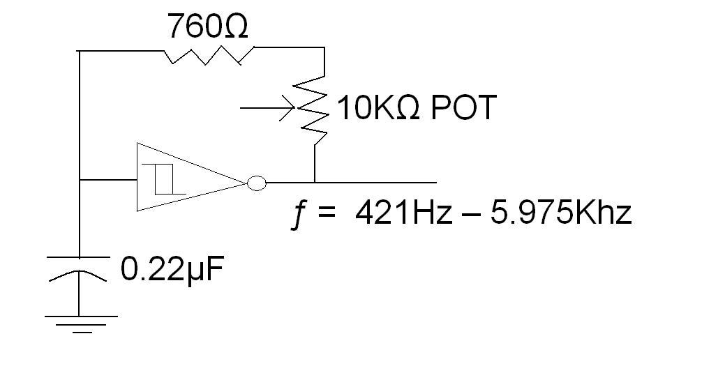
I tried reading the datasheet for MAX7400-7407 but I am confused. Most of the information presented on the datasheet is new to me. From what I understood, the output frequency will = Fclk/100. So I made some adjustments to my circuit below: This would make it less work for the filter. The problem is that the attentuation is greater at higher frequencies than lower frequencies. If you put it through an AGC amplifier after it`s been through the filter then you could hopefully stablise the output amplitude enough. 🔗 External reference
Related Circuits
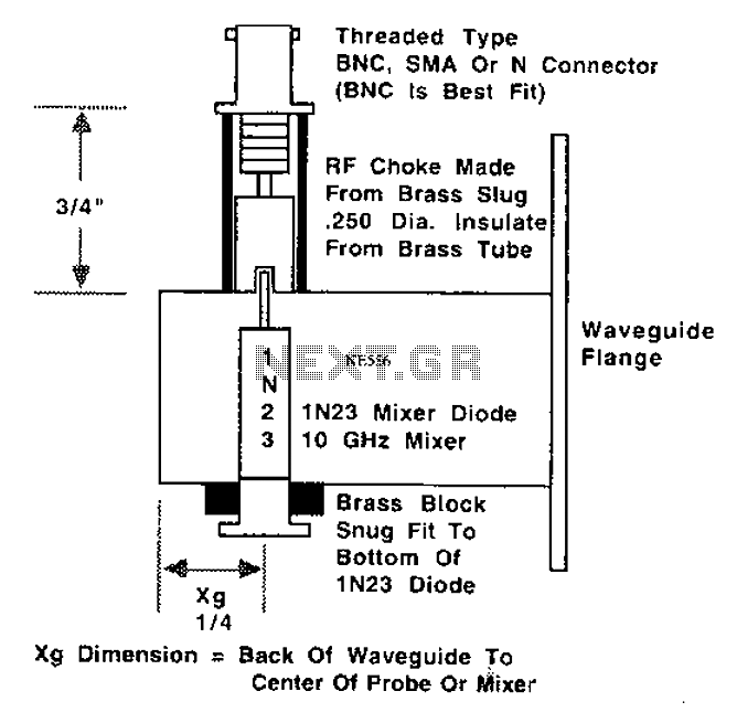
This is a 10 GHz frequency amateur radio waveguide detector. The 10 GHz amateur radio waveguide detector is designed to operate within the microwave frequency range, specifically targeting the 10 GHz band commonly used in various amateur radio applications. The...
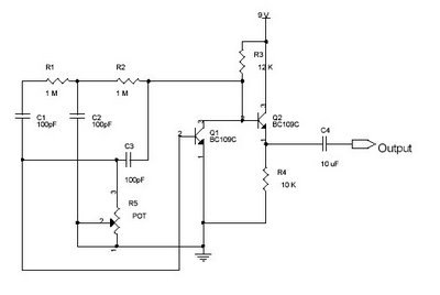
This circuit is a sine wave oscillator with a frequency range from 5 Hz to 5 kHz. The capacitors C1, C2, and C3, with a combined value of 100 pF, produce a frequency of 5 kHz. To achieve different...
This circuit generates an accurate and adjustable sine-wave output by removing harmonics from a square wave. This circuit utilizes a harmonic filter to transform a square wave input into a sine wave output. The primary function of this circuit is...
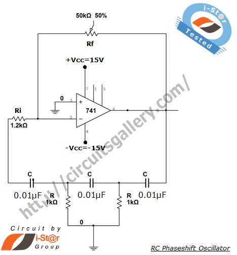
A phase-shifted oscillator can be constructed using a basic operational amplifier (op-amp), three resistors, and three capacitors. One of the resistors should be adjustable, while the other components should have the same value. This oscillator design exhibits low distortion...

The circuit primarily comprises several coils, a step-up power transformer, and a capacitor. Power from an AC wall receptacle is supplied to transformer T1 (a small neon-sign transformer), which increases the voltage to approximately 3000 volts AC. The output...
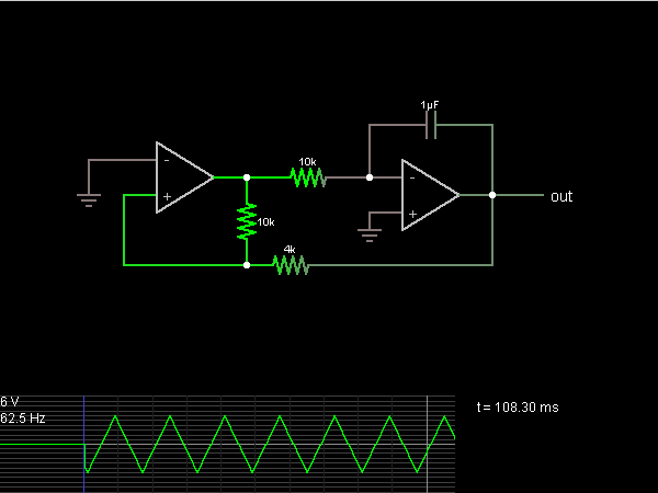
The second half of the circuit is an inverting integrator. The first operational amplifier (op-amp) begins with its two inputs in an unknown state; it can be assumed that it starts with the non-inverting input slightly higher than ground....