
Square Tesla Coil

The schematic of the rotary spark gap is illustrated as a separate unit. It includes a 12-volt power transformer, a bridge rectifier, a 4700 µF capacitor, and a 12-volt DC motor. Power is supplied to the circuit through a 115-volt AC line cord, ensuring the necessary voltage for operation.
The Tesla Coil operates on the principle of resonance, where the electrical energy oscillates between the primary and secondary coils. The precise tuning of L3 is crucial for achieving resonance, as it directly affects the energy transfer efficiency. The spark gap serves as a switch that allows intermittent discharge of energy from the capacitor, creating high-voltage pulses that resonate through the coils. The design of the coils, including their turns ratio and materials, is optimized to maximize voltage output while minimizing energy losses due to resistance.
In practical applications, the rotary spark gap enhances the reliability and consistency of the Tesla Coil's operation, allowing for continuous adjustments to output without the need for frequent manual intervention. This adaptability is particularly beneficial in experimental setups where varying energy levels are required. The integration of a high-capacitance capacitor and a robust transformer ensures that the system can handle the high voltage and current demands, providing a stable and powerful source of electrical energy for various applications, including demonstrations of high-voltage phenomena and experimental physics.The circuit consists of little more than a few coils, a step-up power transformer, and a capacitor. Power from an AC wall receptacle is fed to transformer T1 (a small neon-sign transformer) which steps the voltage up to about 3000-volts AC. The stepped-up output of T1 is fed through L1 and L2 across C1, causing it to charge until enough power is stored in the
unit to produce an arc across the spark gap. The spark gap-which momentarily connects C1 and L3 in parallel-determines the amount of current transferred between C1 and L3. The arcing across the spark gap sends a series of high voltage pulses through L3, giving a sort of oscillating effect.
The energy fed through L3 is transferred to L4 via the magnetic coupling between the two coils. (Because of the turns ratio that exists between L3 and L4, an even higher voltage is produced across L4)> Coil L4 steps up the voltage, which collects on the top-capacitance sphere where it causes an avalanche breakdown of the surrounding air, giving off a luminous discharge. In order to get maximum output from the Tesla Coil, certain conditions must be met. First of all, the primary and secondary resonant frequencies must be made equal by tuning the primary coil, L3.
That`s accomplished by tapping L3 at points along the coil with a clip. In addition, the setting of the spark gap greatly effects the output of the Tesla Coil. Our Tesla Coil is designed to use either a stationary spark gap or an optional rotary spark gap; both of which must be adjusted for maximum output. (We`ll discuss the rotary spark gap a little later. ) If L3 and L4 are coupled too close, coil efficiency is reduced; over-coupling prevents the circuit from resonating at maximum efficiency.
That also causes a breakdown between L3 and L4, which can produce arcing between the two coils. By increasing the coupling between L3 and L4, the amount of energy increases in L4 until a "critical coupling" is reached. In addition, the Q of the coils is very important (the Q of a coil is equal to its inductive reactance divided by its resistance).
The lower the Q, the higher the efficiency of the coil. The primary coil was made from a few turns of aluminum grounding wire (so its resistance is very low). The secondary has many more turns of fine magnet wire, which by its very nature exhibits a higher resistance than does the wire used in the primary coil(L3).
The rotary spark gap is a simple add-on circuit for the Tesla Coil, consisting of a variable DC power supply, and a small, 5000-rpm dc motor. The circuit allows you to vary the output of the Tesla Coil by adjusting the rotating speed of the motor.
A rotary spark gap because the stationary gap could cut out, requiring that the gap be re-adjusted. Figure 2 shows the schematic diagram of the rotary spark gap, which is assembled as a separate unit. The circuit is made up of a 12-volt power transformer, a bridge rectifier, a 4700uF capacitor, and a 12-volt dc motor. Power is delivered to the circuit via a 115-volt AC line cord, and fed to t 🔗 External reference
Related Circuits
The RF oscillator using the inverter N2 and 10.7MHz ceramic filter is driving the parallel combination of N4 to N6 through N3. Since these inverters are in parallel, the output impedance will be low so that it can directly...
A basic square wave generator has been designed to operate a speedometer circuit board, which is responsible for controlling various functions. The square wave generator circuit typically consists of a few key components: a timer IC, such as the 555...
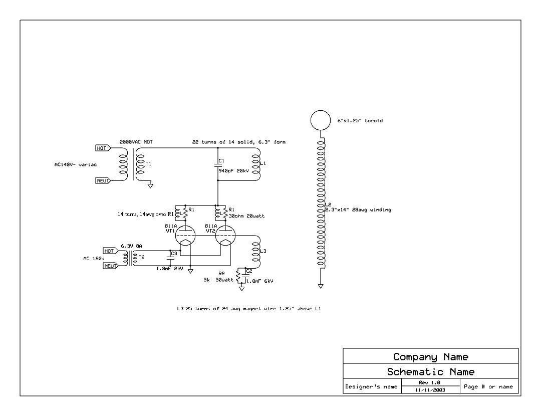
This is the specific schematic for the Tesla Coil that will be constructed. The design was created by Steve Ward. The Tesla Coil is a resonant transformer circuit that generates high-voltage, low-current, high-frequency alternating current electricity. It operates on the...
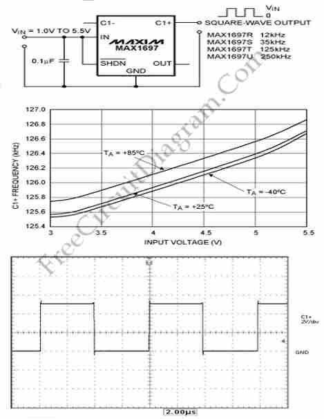
This circuit generates a square wave, which is useful as a clock signal or AC drive for the excitation of sensors. This article presents a square wave. The square wave generator circuit is designed to produce a periodic waveform that...
This is a low-cost accurate square-root circuit. This circuit is used to provide a square-root function with good accuracy. The benefit of this circuit is its affordability and precision. The low-cost accurate square-root circuit typically employs operational amplifiers (op-amps), resistors,...
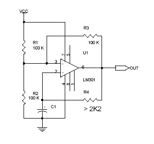
This circuit utilizes the Op-Amp LM301 to generate a simple square wave. The LM301 operates with a power supply range of 3 V to 36 V and can handle a maximum frequency of 325 kHz. The oscillation frequency is...
Warning: include(partials/cookie-banner.php): Failed to open stream: Permission denied in /var/www/html/nextgr/view-circuit.php on line 713
Warning: include(): Failed opening 'partials/cookie-banner.php' for inclusion (include_path='.:/usr/share/php') in /var/www/html/nextgr/view-circuit.php on line 713