
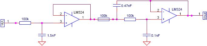
Ssb/Cw Product Detectors

The circuits designed for the detection of single-sideband (SSB) and continuous wave (CW) signals are essential in various communication applications. These circuits leverage the principle of modulation and demodulation to extract information from the modulated carrier wave. The primary component in these circuits is the beat frequency oscillator (BFO), which plays a crucial role in the demodulation process.
The BFO generates a signal that mixes with the incoming SSB or CW signal. The injection level of the BFO, typically ranging from 0.5 to 1 V rms, ensures that the mixing process effectively produces the desired output without introducing excessive noise or distortion. This voltage level is critical for maintaining the integrity of the signal during detection.
Operating at frequencies up to approximately 25 MHz, these circuits must be designed with careful consideration of frequency response and bandwidth. The choice of components, such as filters and amplifiers, is vital to ensure that the circuit can handle the high-frequency signals while minimizing interference and maximizing sensitivity.
In practical applications, these circuits are commonly found in receivers for amateur radio, military communication systems, and other RF applications where SSB and CW signals are prevalent. The design must also consider factors such as impedance matching, power supply requirements, and thermal management to ensure reliable operation across the specified frequency range. These circuits are used for product detection of single-sidebound (SSB) and CW signals. BFO injection is typically 0.5 to 1 V rms for both circuits. Frequencies can be up to 25 MHz or so.
Related Circuits
The circuit presented is a metal detector that operates based on the superheterodyne principle, which is commonly utilized in superhet receivers. It employs two RF oscillators, both fixed at a frequency of 5.5 MHz. The first RF oscillator consists...

This transducer is from a humidifier and operates at 48 kHz. It includes a driver circuit and has easy access for modifications. The process of disassembling one of the two transducers suggests that the circuit board may be difficult...
The sensitivity of the gate terminal to voltage changes is significant. In this configuration, the gate terminal is left open circuit and connected only to a probe, which consists of a few inches of bare copper wire. Without a...
The HCS12 series of microcontrollers does not include dedicated internal digital-to-analog conversion hardware. Therefore, external hardware, such as a digital-to-analog conversion integrated circuit (IC), is required. To implement digital-to-analog conversion (DAC) in systems utilizing the HCS12 microcontroller, an external DAC...
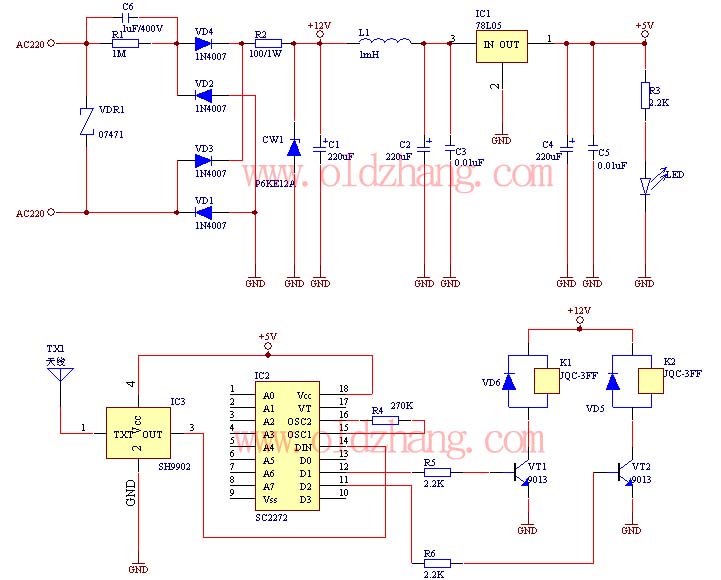
The production of this wireless remote control switch is relatively straightforward. All component parameters have been tested and verified. The installation of the reader component parameters can be completed during production, including the soldering of resistive and capacitive components...
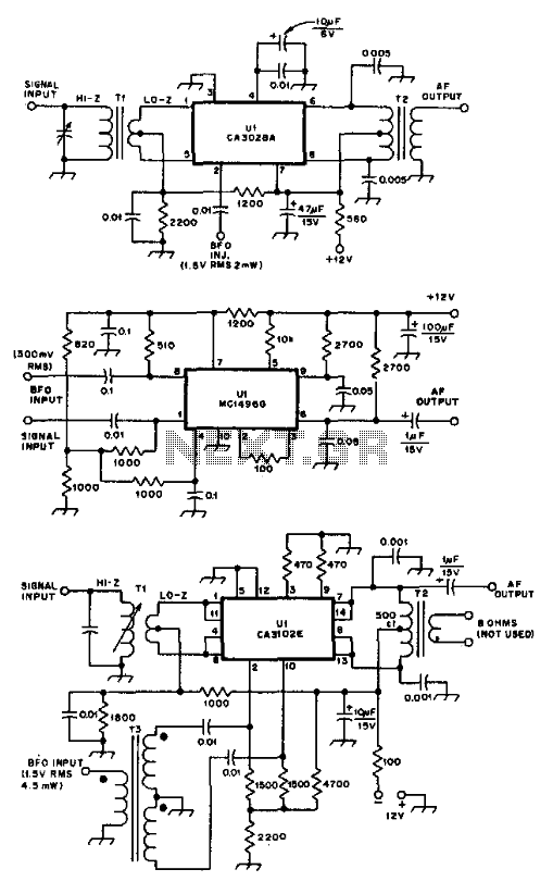
These product detectors utilize integrated circuit (IC) devices. They are capable of detecting single sideband (SSB) and continuous wave (CW) signals. The circuits are designed to operate effectively up to frequencies of 20 or 30 MHz. T3 in the...