
Stall Matrix
The design of the Diode Matrix switch machine control system employs a straightforward yet effective approach to managing multiple turnout operations within a model railway layout. The use of the LM556 timer integrated circuit provides reliable control of the stall motor switch machines, allowing for precise activation and deactivation of turnouts based on user input through push buttons. Each track selection is clearly indicated through the logic block diagram, which simplifies troubleshooting and understanding of the circuitry.
The inclusion of a truth table within the schematic enhances user comprehension by providing a quick reference for turnout positions based on track selection. The optional Master Throw Button adds a layer of safety and functionality, preventing unintended turnout movements during track changes, which is crucial for maintaining operational integrity in complex layouts.
Furthermore, the flexibility of the design allows for multiple configurations, accommodating various layouts and operational preferences. The ability to connect separate matrix systems at either end of a double-ended yard enhances usability, offering operators the choice of controlling the entire yard from either end, thereby promoting efficiency and ease of use.
The current handling capacity of the LM556 timers facilitates the control of multiple switch machines, with the potential for adding visual indicators such as LEDs to signal the status of each turnout. The low current requirements of the diode matrix system permit the use of signal diodes, which are more compact and efficient than higher-rated diodes typically used in heavier current applications.
Overall, this Diode Matrix switch machine control system exemplifies an advanced yet user-friendly solution for model railroad enthusiasts, ensuring reliable operation while minimizing the risk of electrical noise interference. It is advisable to conduct thorough testing and experimentation with the circuit before full-scale implementation to ensure optimal performance and reliability in the intended application.The circuits on this page are basic designs for "Diode Matrix" switch machine control systems that can be used to operate "Stall Motor" switch machines in `Ladder` type storage yards or other multiple turnout areas. The principle for these diode matrix circuits on this page is very much the same as for those used to control twin coil type switch
machines except that the diodes handle much lower currents. The following diagram is for the circuitry of the 556 - Switch Machine Drivers. On the Diode Matrix system schematics these circuits are represented by a logic block diagram in order to simplify the diagrams. Tracks 1 through 4 are selected with the appropriate push buttons. This in turn SET`s or RESET`s, through the diode matrix, the appropriate switch machine motor controller to its "N" or "R" condition and operates the turnouts.
Included in the diagram is a "Truth Table" that shows the position of each turnout for the particular track that is selected. The "X" or "DON`T CARE" symbol means that it does not matter where that turnout is lined to if track 1 or 2 is selected.
In the following diagram; extra diodes, as indicated by the dashed lines on the schematic, have been added so that the turnouts above a selected track are moved to their "N" positions when the lower track`s button is activated. This means that if a double ended yard had separate matrix circuits at each end - these could be connected together so that both ends of the yard could be operated from the matrix selector at either end if desired.
When the tie switches are open the turnouts at the each end of the yard are operated by their respective matrix systems. When the tie switches are closed the turnouts in the yard can be operated from either end. Two options for connecting the separate matrix systems are shown. For Track 1 the connection is at one location only. For TRACK 2 the connection can be made from either end of the yard. The only limitation to cross coupling is that both ends of the yard should be symmetrical as would be the case in the diagram shown at the bottom of the schematic.
The "Master Throw Button" is an optional device but it does prevent the turnouts from moving as the rotary switch is moved from one selection to the next. The button also allows route to be pre-selected. Interlocking train detection circuits could be tied into Master Throw Button to automatically operate the turnouts or prevent them from throwing if they are blocked by a train or signal system.
If you would like to make use of this type of circuit, please take the time to build one and do some experimenting before actually installing them on your layout. This will give you a better understanding of the circuits and can save a lot of frustration down the line.
The maximum current the the outputs of the LM556 timers can source or sink is 200 milliamps. These circuits could, in theory, control 10 or more Tortoise ™ switch machines. Also additional LED`s could be connected to the outputs. The matrix diodes in these circuits have to carry less than one-half of a milliamp compared to four or five amps with twin coil machines. This allows the use of low power `signal` diodes for this application. Due to the design of this type of system and the use of stall motor switch machines any number of turnouts can be thrown at the same time because none of the motors has to share a limited amount of power from a capacitor as is the case with twin coil / diode matrix control systems.
In fact, due to the nature of the stall motors used in these switch machines the entire switch control system draws less current when the motors are in motion than when they are stalled at the ends of their travel. In order to reduce the possibility of electrical noise causing false turnout throws care should be taken when routing the matrix control wiring.
If possible keep the push buttons, diode matrix and motor driver blocks as close together 🔗 External reference
Related Circuits
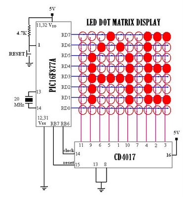
Multiplexed displays are electronic displays where the entire display is not driven simultaneously. Instead, sub-units of the display—typically rows or columns for a dot matrix display or individual characters for a character-oriented display—are multiplexed. This means that they are...
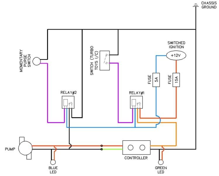
Coolingmist Stage 3 HOM Trunkmount kit installation is underway to enable continuous enjoyment of the HOM system. The setup includes a switch for arming the system and a separate push-button for purging. The intercooler sprayer assembly will be removed...
In single-phase AC induction motors, commonly found in refrigerators and washing machines, a start winding is utilized during the initial starting phase. Once the motor reaches a specific speed, this winding is deactivated. The start winding operates slightly out...
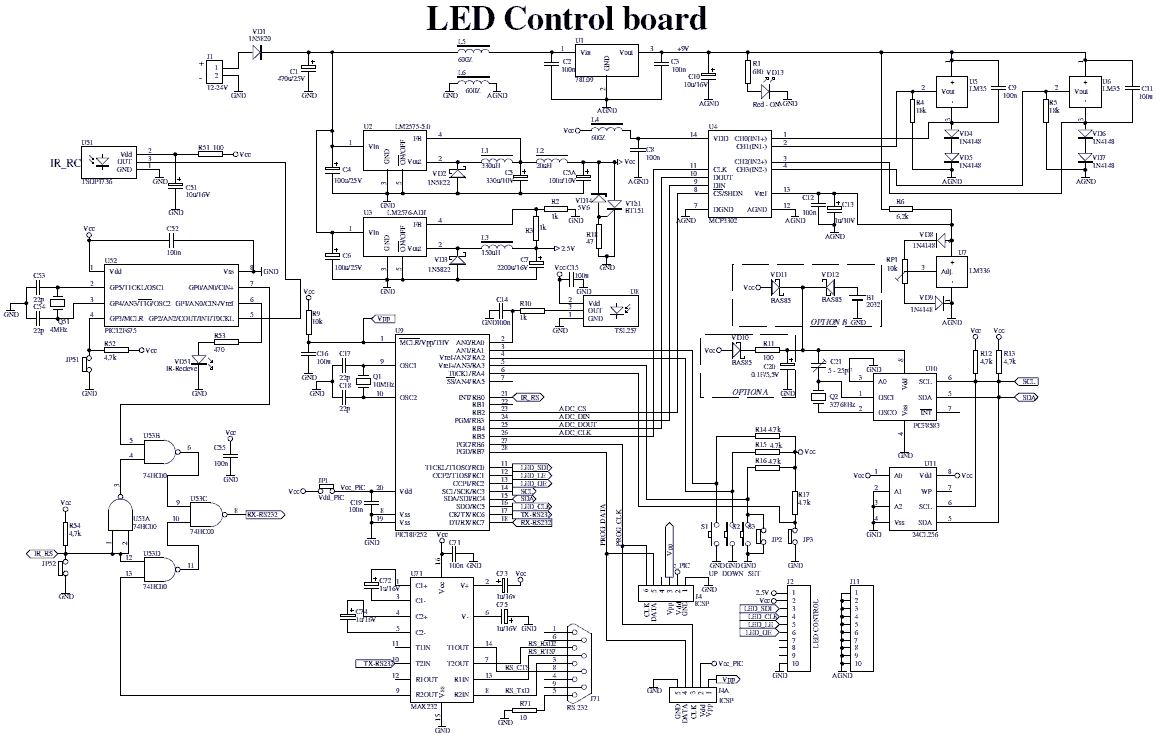
The device comprises two parts: LED control board and LED display board. The two PCBs are designed to fit together one behind the other using two sets of dual row connectors and 4 spacers. One of these connectors is...
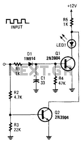
This circuit can be utilized to detect a stuck output or node in a circuit, or a loss of data or pulses. The pulse train charges capacitor C1 and biases transistor Q1 on, which illuminates the LED. If the...
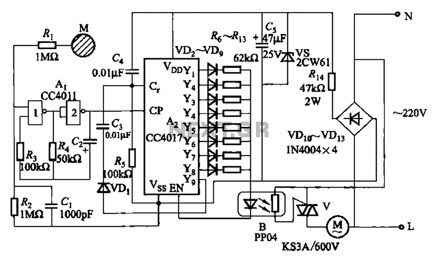
The circuit depicted in Figure 3-7 utilizes a touch sensor chip in conjunction with a conductive sheet. It is designed to achieve eight different speed settings. The CC4011 timing pulse oscillator is comprised of an integrated circuit. The configuration...