
Stand-by Battery Charger
The circuit is designed to function as a battery eliminator, providing a stable output voltage of 7.5V for low power applications. The primary component, T1, is a transformer that steps down the mains voltage (230V AC) to a lower AC voltage (10V AC) suitable for the circuit's requirements. The output from the transformer is fed into a bridge rectifier formed by diodes D1 to D4 (1N4002), which converts the AC voltage to a pulsating DC voltage.
The pulsating DC is then smoothed by the electrolytic capacitor C1 (1000µF, 16V), which reduces the ripple voltage and provides a more stable DC output. Following this, a zener diode (D6, 8.2V, 0.4W) is used in conjunction with a series pass transistor (Q1, BD139) to regulate the output voltage. The zener diode ensures that the voltage remains stable at 7.5V by shunting excess voltage away from the output during normal operation.
In the event of a mains power failure, the circuit includes a standby battery (B1, 5x1.5V) connected in series with diode D7. This diode allows the battery to take over and supply power to the load while preventing backflow into the circuit. The voltage drop across D7 reduces the effective output voltage to approximately 7V when the battery is supplying power.
Resistor R3 serves a dual purpose; it is used to trickle charge the standby battery when the circuit is powered by mains. The proper value of R3 can be calculated by determining the voltage difference between the zener voltage and the battery voltage, then dividing this by the desired trickle charging current, which is approximately 0.7 mA.
The complete part list includes resistors (R1, R2, R3) rated at 1k ohm, a red LED (D5), a 50mA fuse (F1), capacitors (C1, C2 rated at 1000µF and 100µF respectively), the zener diode (D6), the transistor (Q1), diodes (D1 to D4 and D7), and the transformer (T1). This configuration provides a reliable power supply solution for low power electronic devices, effectively eliminating the need for a conventional battery while ensuring seamless operation during power outages.This simple circuit will find many applications as a battery eliminator for low power requirements. It consists of a transformer, a bridge rectifier and an electrolytic capacitor followed by a zener controlled series pass transistor. The output is stabilized at +7.5V. The stand-by battery, 7.5V, in series with D7, floats across the output terminals, ready to take over in case of main failure.
The voltage drop across D7 will then reduce the power supply to about 7V. The R3 has an additional function, when working off the mains it will trickle charge the dry cells or storage battery. It?s correct resistance can be found by dividing the voltage potential difference between the zener D6 and the battery by the safe trickle current, which may amount to some 0.7 milliamps.
Part List R1-2-3=1Kohm D5=Led Red 3mm F1=50mA Fuse C1=1000uF 16V D6=8V2 0.4W zener B1=5X1.5V Battery C2=100uF 16V Q1=BD139 D1...4-7=1N4002 T1=230Vac// 10Vac - 0.5A transform. 🔗 External reference
Related Circuits
This circuit provides an initial voltage of 2.5V per cell to quickly charge a car battery. The charging current decreases as the battery charges, and when the current drops to 180 mA, the charging circuit reduces the output voltage...
The USB charger power supply is designed for use in MP3 and MP4 chargers. It accepts an input of AC 160-240V at 50/60Hz and has a rated output of DC 5V at 250mA. For applications requiring a long-term higher...
The circuit is designed to charge a 12-volt component selection at a maximum current of six amperes. Once the battery voltage reaches its fully charged level, the SCR shuts off, and a trickle charge, determined by the resistance value...
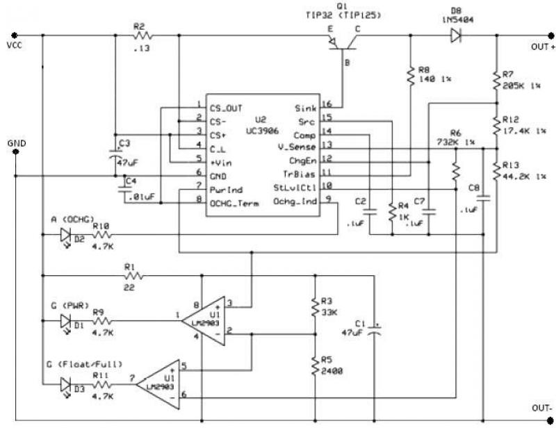
The UC3906 battery charger circuit controller includes all necessary circuitry to manage the charge and hold cycles for sealed lead-acid batteries. This circuit is specifically designed to deliver the appropriate charging voltage and current based on the battery's temperature...
This document presents a schematic diagram of an electret microphone pre-amplifier utilizing the LMV721 operational amplifier. The LMV721 is chosen for its low noise and low power characteristics. The electret microphone pre-amplifier circuit is designed to amplify the weak audio...
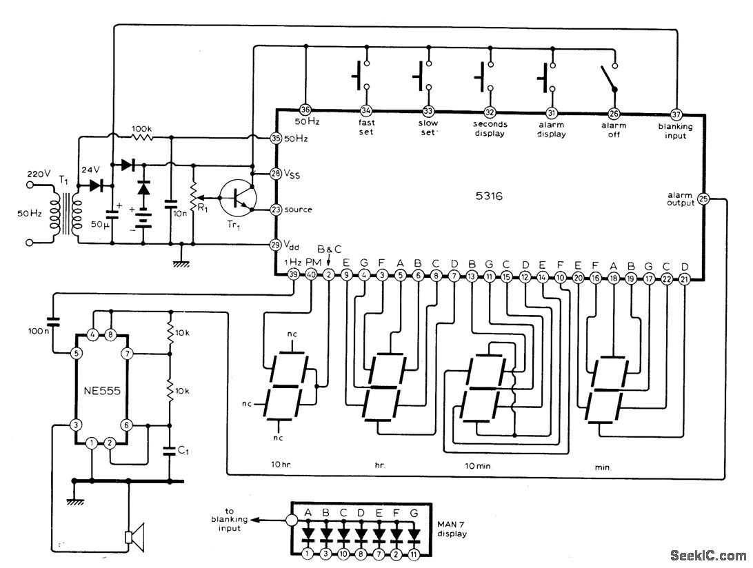
The circuit utilizes the MM5316 alarm-clock integrated circuit (IC), which is originally intended for driving LCD or fluorescent displays. In this implementation, it has been adapted for use with LED display diodes. The system is designed to operate on...