
STRESS METER
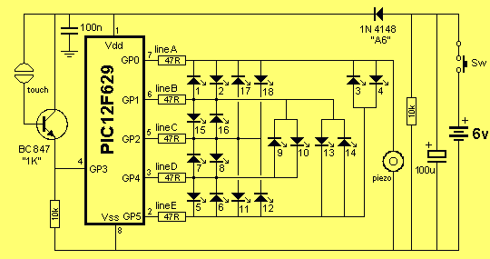
The described circuit features a circular arrangement of 16 Light Emitting Diodes (LEDs) that are controlled to create a visual chaser effect. The LEDs are likely connected in a series or parallel configuration to a microcontroller, which manages the sequencing and timing of the illumination. The circuit includes two capacitive touch pads, which serve as input devices to initiate the LED sequence. When a user touches one of the pads, the microcontroller activates the LEDs in a sequential manner, producing a chaser effect that progresses around the circle.
Each time an LED is illuminated, an audible beep is generated, likely through a piezo buzzer or a small speaker connected to the microcontroller. This auditory feedback enhances user interaction and engagement with the circuit. The microcontroller is programmed to gradually slow down the chaser effect, ultimately stopping at a random LED. This feature introduces a stress indicator element to the design, as the final illuminated LED is meant to represent the user's stress level.
The program controlling this circuit is already functional but is open to enhancements. Potential improvements could include the addition of varying chaser patterns, customizable stress indicators, or even integrating a display to provide more detailed feedback. The modular nature of the program allows for easy incorporation of new features, encouraging further development and creativity in the design process.
Overall, this circuit exemplifies an interactive and visually engaging project that combines basic electronics with programming, providing a platform for educational exploration and innovation.It consisted of 16 LEDs in a circle with two touch pads. By placing your fingers on the touch pads, the circuit started and ran the LEDs in a "chaser" pattern around the display, with a beep each time a LED was illuminated. The circuit gradually slowed down to a random LED and the display showed "how stressed you were." "What a wonderful idea for the 18 LED Display-1" I thought.
The program for this game is complete and ready to run, but it can be improved and more features can be added. This is the purpose of this article. After you see how the sub-routines are put together, you are invited to add more ideas of your own. Whe 🔗 External reference
Related Circuits
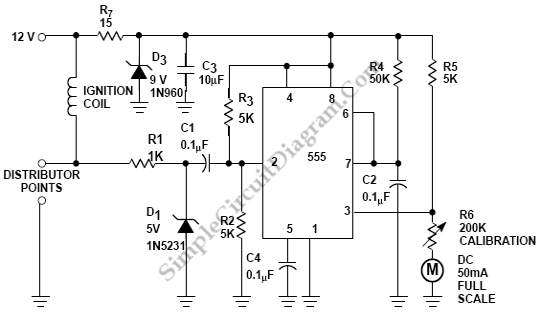
Pulses are received by the timer from the distributor points. When the timer output is high, Meter M receives a calibrated current through R6. The meter does not... The circuit described involves a timer that receives pulse signals from distributor...
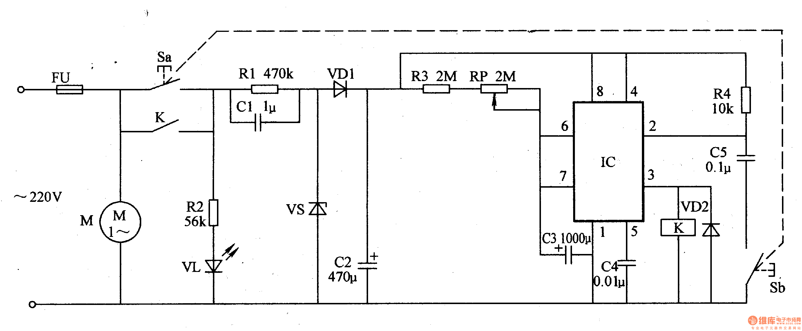
The thermometer meter slinger circuit consists of a power supply circuit and a meter slinger timing control circuit, as illustrated in figure 9-135. The power supply circuit includes a fuse (FU), power supply buttons (S - Sa, Sb), resistors...
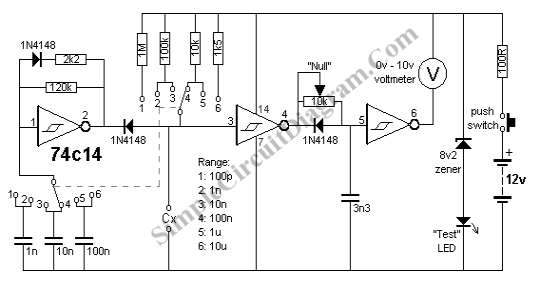
A capacitance meter is an essential instrument for electronics hobbyists and professional electronic technicians. A capacitance meter is a specialized device used to measure the capacitance of capacitors in electronic circuits. It is a valuable tool for diagnosing and troubleshooting...
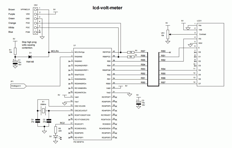
Any PIC microcontroller equipped with an ADC and sufficient memory to accommodate the program can be utilized. An LED is pulsed after each ADC acquisition to indicate the processor's activity, allowing for verification of software functionality. The LCD voltmeter...
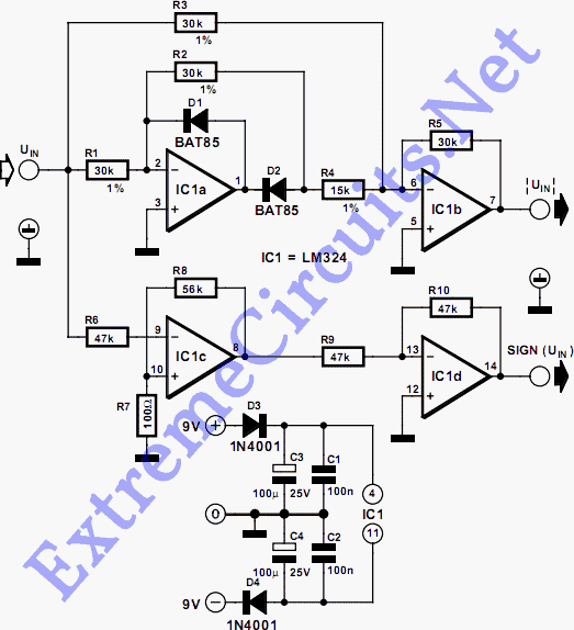
This circuit separates an input voltage signal into its components: (1) the absolute value and (2) the polarity or 'sign' (+ or -). It is designed to handle direct current (DC) signals. The circuit operates by utilizing operational amplifiers (op-amps)...
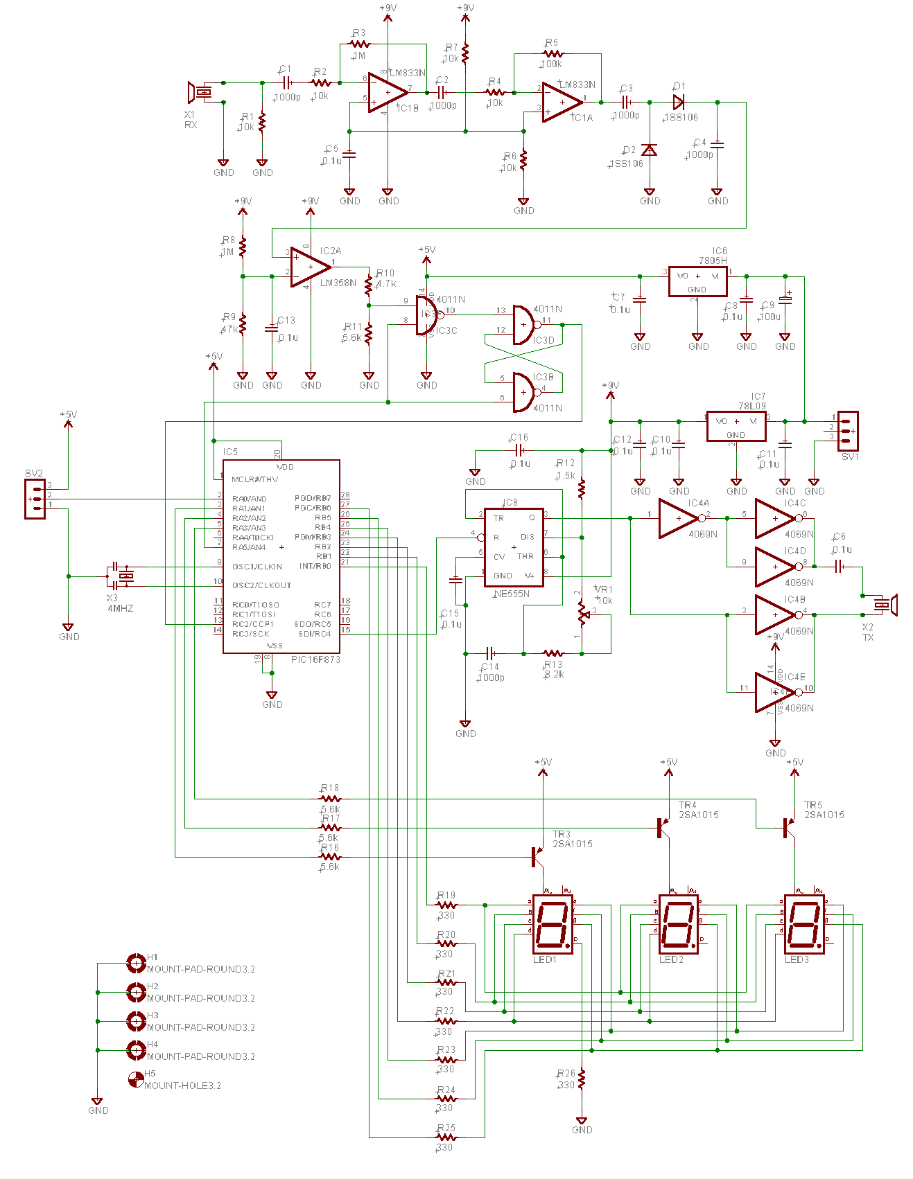
The oscillation circuit of the transmitter was added. An oscillation circuit using a 555 IC is implemented for a modified circuit. This allows for easy adjustment of the oscillation frequency, necessitating changes to the software. The described circuit employs the...