
Structure and working principle of brushless motor windings

The brushless motor operates on the principle of electromagnetic induction, where the interaction between the stator's rotating magnetic field and the rotor's magnetic field generates motion. The triangular coils are arranged in a specific configuration to optimize the magnetic field's efficiency and performance.
In a brushless motor, the stator consists of multiple windings, often arranged in a triangular pattern, which allows for effective magnetic field generation. The switching mechanism, usually implemented through a series of transistors, controls the timing and sequence of current flow through these windings. This control is crucial, as it determines the direction and speed of the rotor's rotation.
A drive control circuit is essential for managing the switching of the transistors. This circuit typically includes a microcontroller or dedicated driver IC that interprets input signals (such as speed commands) and generates the appropriate control signals to the transistors. The design of the control circuit must ensure that the transitions between different states are smooth and efficient, minimizing losses and maximizing performance.
The triangular coil design not only enhances the motor's efficiency but also contributes to its compact size, making brushless motors suitable for a wide range of applications, from small electronic devices to large industrial machinery. The absence of brushes in these motors reduces maintenance needs and increases reliability, further solidifying their preference in modern engineering solutions.Structure and working principle c brushless motor windings Structure and working principle of the triangular coils As shown, through the switch, you can make the stator coil current cycle turned, and the formation of a rotating magnetic field. Can be seen from the figure, the cycle of the week and the current state of the switch path. Is usually caused by switching of the switching transistor, the switch in order to achieve an orderly transition must have a drive control circuit. i class = "else" IC inventory | Part Search | Gallery | Community | 21IC official microblogging |
Related Circuits
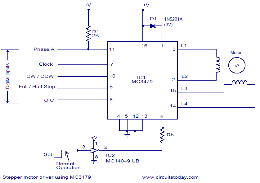
The circuit diagram presented is for a stepper motor driver utilizing the MC3479 integrated circuit from Motorola. The MC3479 is specifically engineered for driving a two-phase stepper motor in bipolar mode and is available in both standard DIP and...
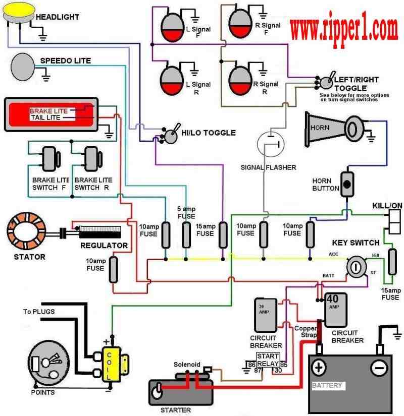
Customs by Ripper - A technical page focused on basic wiring for any vehicle, particularly motorcycles. The page serves as a valuable resource for individuals seeking to understand the fundamentals of vehicle wiring, with a specific emphasis on motorcycles....
To control a stepper motor, each winding must be energized individually in a specific and timed sequence. This energization is carried out by a driver circuit, which acts as an amplifier. The timing is managed by an indexer circuit,...
This project outlines the construction of a Brushed Motor Electronic Speed Controller (ESC) for cars and boats using a Microchip 12F675 PIC and a limited number of standard components. This ESC is a revised version of an earlier aircraft...
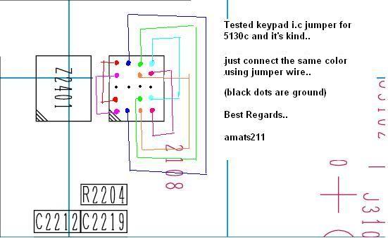
The Nokia 5130 keypad jumper requires following a specific diagram. It has been tested recently, and after implementing the jumper, all keypads are functioning correctly. The Nokia 5130 mobile phone features a keypad that can occasionally experience issues due to...
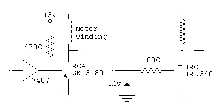
This is a reverse-engineered circuit diagram of a one-transistor circuit commonly used to drive permanent magnet DC motors in children's toys. This circuit typically employs the 625mW version of the widely used 8050 or 8550 transistor. It is important...