
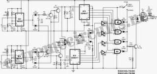
Telephone control automatic lamp circuit 1

The circuit employs a photosensitive resistor and a transistor to facilitate telephone and light control. The design ensures that during the day, the light remains off despite incoming calls due to reduced sensitivity from ambient light. At night, the increased resistance allows the light to activate upon receiving a call. Once the call is finished, the lamp remains lit briefly before turning off, allowing for a delay in power consumption. A button (SB) can also be used to turn on the light manually, similar to a standard delay light mechanism. The circuit includes features for light sensitivity adjustment and energy storage, ensuring reliable operation during subsequent calls.
The automatic light system utilizes various electronic components to ensure seamless integration with the telephone system. The key components include:
1. **Telephone Line Interface**: The circuit connects in series with the telephone line, allowing it to detect ringing signals without needing to distinguish polarity.
2. **Control Components**:
- **Diodes (VD7, VD6)**: Used for rectification and protection.
- **Thyristor (VT2)**: Acts as a switch to control the lamp based on the call's status.
- **Optocoupler (4N25)**: Isolates the control circuit from the higher voltage of the telephone line while allowing signal transfer.
3. **Photosensitive Resistor (R1)**: This component adjusts the circuit's sensitivity to ambient light, ensuring the lamp only activates at night.
4. **Transistor (VT1)**: Functions as a switch that is activated by the photodiode's response to the incoming call signal.
5. **Capacitors and Resistors**: These components help manage voltage levels and timing for the circuit's operation, particularly during the transition phases of turning the lamp on and off.
6. **Manual Control**: The SB button allows manual activation of the light, providing flexibility for the user.
The design emphasizes minimal power consumption during idle states and ensures that the lamp remains lit briefly after a call, enhancing usability without compromising energy efficiency. The circuit's architecture is robust, allowing for easy adjustments to sensitivity and response times, making it suitable for various environments. Proper installation is crucial to avoid direct light exposure to the photosensitive resistor, which could lead to erratic behavior. The overall system provides a reliable and user-friendly solution for automatic lighting in conjunction with telephone usage. Automatic light is introduced by the telephone block system, the phone rang that night and asked the owner to pick up the handset or pull L, the lamp will light up; the phone s topped (if no contact) or hang up after the delay l0-40s, lamp white line will be put out off. With this automatic lights at night to call people to ur convenience. In addition, dredging is also provided a light touch of a button, get up at night when the owner, just click keys. It can also lit handsome s. Automatic telephone lamp circuit lhl ~ 23-1, ignored the dotted line in the right part of the general lighting circuit, S for the light switch, closing 1.
After s, the lights - this El} U riding small by ILi then screwed system; open S. Lights off, lights on the control by the telephone r. The imaginary line of the left portion of the telephone control section. VD7 a diode and a thyristor VT2 ~ VD10 composition control switch calling road, blocking diode VD6, regulator vs, capacitors (; constitute a simple resistor drop Ju Wensheng line, output of about 2 -IV blind galvanic twist for electrical control circuit. optocoupler 4N25, i photosensitive electrical resistor RI. and transistor VT1 composition telephone and electric light control path. a, b-side in series with the telephone line, when the series is not necessary to distinguish the positive and negative polarity, when hes not talking, among .h no current flows through the built-in light emitting diode emitting small 1N2 5, which corresponds photodiodes off, thats 4N20, feet off fairly small rise.
VT1 deadline. goods ah tube VT2 off electric lamp E small light. at this time the circuit is in a standstill state, power consumption is minimal, less than found by imA, does not consume electricity that the town can. when a call button or enter the phone is off-hook dialing ah ask a current flow, stack light emitting diode within 4N2j, corresponding to the photodiode chip is turned on, pedicle pin output high.
if during the day, quiet RI. irradiated with light low drought resistance, and wide cattle on low voltage (with respect to the product stare accounting), not enough to make VT] is turned on, so during the day, although a call, the lamp will not light up, only at night, RI. showed high resistance, high voltage share dichotoma above, it makes VT1 conduction, C storage of application, the Netherlands on by v ri, VD5 rapidly charge the f, cz charge to make the right voltage of about 20V celery Meanwhile, f;.
also by R, to the inter-VT2 J cathode discharge, VT2 rapidly outside passage, lamp E lights up after the call is finished hang .al, no current flows between the cut-off but the South to resume .VT1 C. stored charge can lock continued through may. to VT2 provide f J current. therefore, VT2 still holding or pass state lamp still lights up to be so junction beam .VI, losing trigger current when the air flow through the electrical zero that is shut off, turn off the lights.
SB button to turn on the lights to move, when you press the SB, ( j stored charge on the adoption of SB, R: to c charge electric and VI 2 pass, E lamp lights up which is similar to the ordinary principles of delay light phase and it is not room. inner light intensity control, you can always access key lights. VT2 should be 21/6i 6 5 to M ( RiOO-S deletion and other smaller one-way thyristor trigger current .RI.
for the MG45 photosensitive resistor requires light resistance and dark resistance difference between the bigger the better, Note that when you install Yong let it receives natural light into the room, but not by its own direct exposure to light, otherwise the call will be turn on and off flicker, change the value of R can dig heir festival light sensitivity figure C, capacity achieve greater (] .U ~ eF) its date is that it has both double filtering and energy storage function, because the next phone call, VT2 or pass, VT2 drop voltage across that grid is no longer possible control circuitry, then rely on f. the slow release of the charging circuit can be maintained on as normal.
Related Circuits
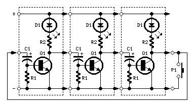
Very simple, versatile modular design. The purpose of this circuit was to create a ring in which LEDs or Lamps illuminate sequentially. Its main feature is a high versatility: you can build a loop containing any number of LEDs...
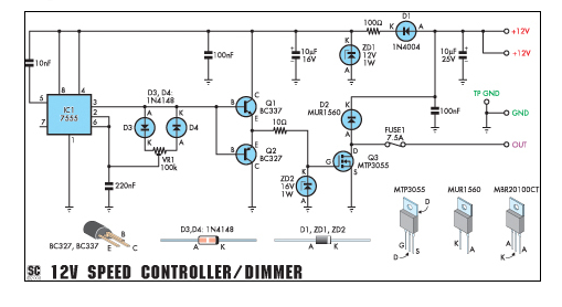
This circuit can function as a speed controller for a 12V motor with a continuous rating of up to 5A or as a dimmer for a 12V halogen or standard incandescent light. The circuit utilizes a pulse-width modulation (PWM) technique...
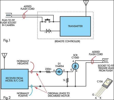
A radio-controlled electronic flash is a valuable tool in any photographer's kit, frequently utilized by professionals. For instance, a wedding photographer may position one behind the bride to illuminate her gown and veil, avoiding visible wires in the shot....
Automatic AC voltage regulator circuit TXD1742 with continuous adjustment. The TXD1742 is an automatic AC voltage regulator circuit designed to provide continuous voltage adjustment, ensuring stable output voltage in varying load conditions. This circuit is particularly useful in applications where...
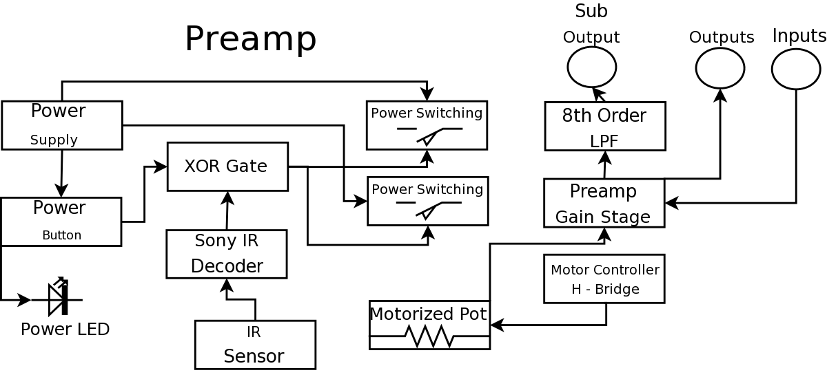
During a Digital Projects Lab, the professor suggested incorporating more circuit-level work into a project. To achieve this, a preamplifier was designed, which included an infrared (IR) remote control to replace a previously built version. The earlier preamplifier functioned...
The following circuit illustrates an Automatic Room Power Control Circuit Diagram. This circuit is based on the NE555 integrated circuit (IC). Features include the use of two Light Dependent Resistors (LDRs). The Automatic Room Power Control Circuit utilizes an NE555...