
FM Telephone Bugs
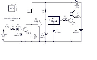
The small telephone bug is a compact and efficient device designed to intercept audio signals from a telephone line and transmit them wirelessly to an FM receiver. This device operates independently using its own power source, eliminating the need for external power supplies. The simplicity of the design is reflected in its low component count, making it an accessible project for electronics enthusiasts.
The circuit typically consists of a few key components: a microphone to capture audio signals, an amplifier to boost the microphone's output, and an FM transmitter circuit to modulate the audio signals onto a radio frequency. The FM transmitter may utilize a simple oscillator circuit, often based on a transistor, to generate the necessary frequency for transmission.
The microphone is usually connected to the amplifier, which enhances the audio signal before it is fed into the FM modulator. The modulator converts the audio signal into an FM signal that can be picked up by standard FM receivers. The entire circuit is designed to operate with minimal power consumption, allowing for prolonged use without frequent battery replacements.
A schematic diagram of the circuit would typically illustrate the connections between these components, highlighting the power supply configuration, signal flow, and any necessary tuning elements to adjust the transmission frequency. This project provides an excellent opportunity to learn about analog audio processing and radio frequency transmission in a hands-on manner.Small telephone bug. Listen telephone line on your FM receiver. It is self powered. Small part count. Circuit diagram, schematics, electronics project.. 🔗 External reference
Related Circuits
This circuit illustrates a remote control system utilizing a radio telephone circuit diagram. Features include the ability to switch appliances from any distance, overcoming various limitations. The remote control circuit employs radio frequency (RF) technology to facilitate wireless communication between...
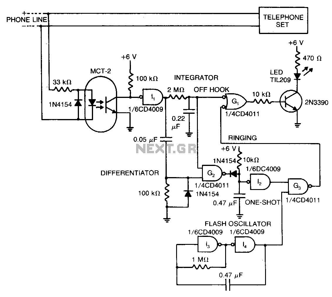
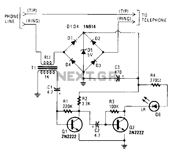
The LED signifies the status of a remote telephone. The light remains off when the phone is hung up. It emits a steady glow when the phone is off the hook, and it flashes intermittently while the phone is...
The incoming ring is detected by transistor T1 and the components connected to it. In the absence of a ringing voltage, transistor T1 is in the off state while transistor T2 is forward biased due to resistor R2 being...
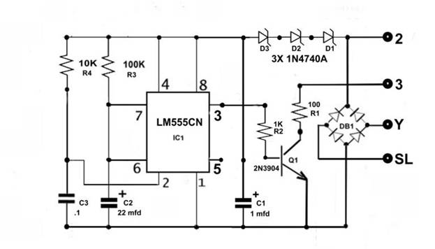
The IR transmitter connects to a telephone circuit and transmits both sides of all telephone conversations to any line-of-sight location within 40 feet. No power is drawn from the central office, as long as all phones remain on-hook. The...
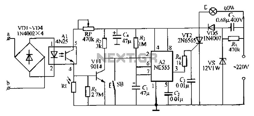
The lamp base circuit integrates an NE555 timer and optocouplers to automatically activate the light when a phone call is received at night. The lamp will self-extinguish after a delay. Additionally, a switch allows manual control of the lamp....
Several weeks ago, a situation arose where there were no telephones left to restore. All payphone projects had been completed and were now collecting dust on shelves. A desire emerged to create a unique, creative, and useful project for...