
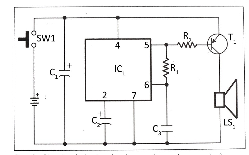
Telephone Ringtone Generator

The telephone ring tone generator circuit typically includes a few key components: a microcontroller or a simple oscillator circuit, a resistor, a capacitor, and a speaker or piezo buzzer. The microcontroller or oscillator generates a square wave signal, which mimics the ringing tone of a telephone. The output frequency of this signal is crucial, as it must replicate the typical ringing frequency of standard telephones, usually around 20 Hz to 30 Hz.
Power supply considerations are important, as the circuit operates within a voltage range of 4.5V DC to 12V DC. This allows for flexibility in power source selection, whether from batteries or a DC power supply. The components must be rated appropriately to handle the voltage and current levels involved.
The circuit can be designed to include a variable resistor (potentiometer) to adjust the tone's volume, allowing for customization based on user preference. Additionally, capacitors may be used to filter the output signal, ensuring a clean sound without distortion.
In practical applications, this ring tone generator can be integrated into various devices that require a ringing sound, such as alarm systems, intercoms, or even DIY telephone systems. The simplicity of the design makes it suitable for educational purposes as well, providing an excellent project for those learning about basic electronics and sound generation.
Overall, the telephone ring tone generator circuit is an efficient and straightforward solution for generating a recognizable ringing sound, making it a valuable addition to various electronic projects.Telephone ring tone generator circuit, built with only several components. It generates simulated telephone ring tone and requires 4.5V DC to 12V DC voltage 🔗 External reference
Related Circuits
This circuit attempts to liven up mono sound sources by simulating a stereo signal. It does this by shifting certain frequencies between left and right to fool the ear. It can often produce a passable mock stereo sound to...
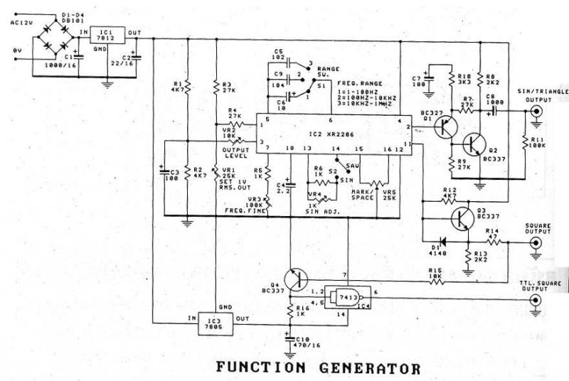
The XR2206 Function Generator is a versatile waveform generator capable of producing sine, triangle, and square waveforms. It operates within a frequency range of 1 Hz to 1 MHz, with frequency adjustments facilitated by variable resistor VR3. The output...
This circuit generates a stable 1 kHz sine wave using the inverted Wien bridge configuration (C1-R3 & C2-R4). It features a variable output, low distortion, and low output impedance to ensure good overload capability. A small filament lamp provides...
Have you ever been using the modem or fax and someone else picks up the phone, breaking the connection? Well, this simple circuit should put an end to that. It signals that the phone is in use by lighting...
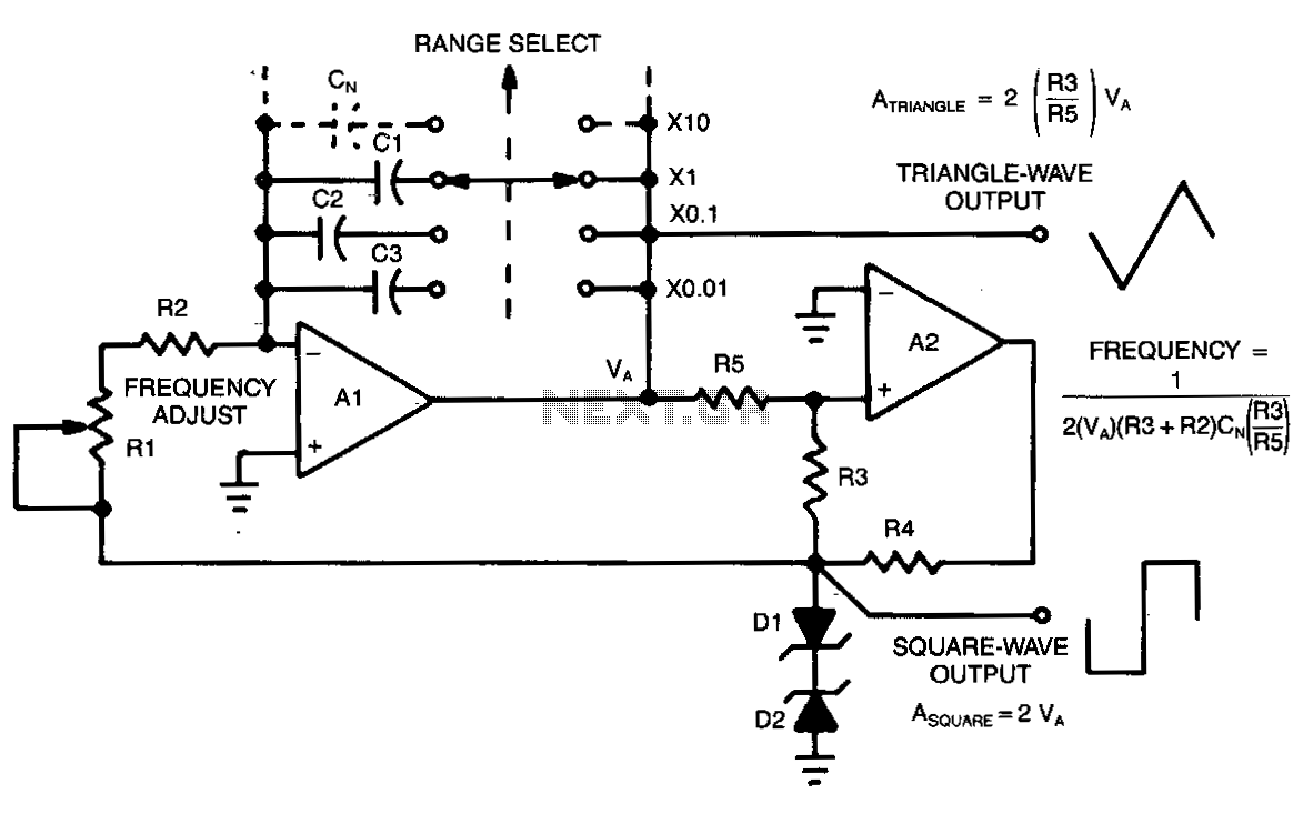
This circuit allows for continuous variation of the frequencies of the triangle and square waves produced, covering a full decade. When the resistance of RS is approximately equal to R3, the amplitudes of the two waveforms will be equal...
This document presents a verified circuit diagram for a simple, interesting, and cost-effective electronic clapper (sound generator) circuit, along with a description of its functionality. The electronic clapper circuit is designed to activate sound generation through the detection of sound...