
The Fetzer Valve
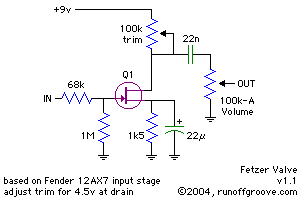
The circuit described is a JFET-based input stage designed to emulate the characteristics of a traditional tube amplifier input, particularly that of a Fender amplifier. The primary goal of this design is to achieve a similar performance in terms of gain, impedance, and frequency response while leveraging the advantages of solid-state technology. The JFET is chosen for its voltage-controlled operation, which mimics the behavior of the triode in a tube amplifier.
The circuit operates with two input configurations: a Low Gain input and a High Gain input. The Low Gain input utilizes a resistive divider to attenuate the signal by 6 dB, making it suitable for high-output sources such as electric guitars. The impedance presented to the guitar is low, which helps to maintain signal integrity and reduce loading effects. In contrast, the High Gain input allows for a direct connection with a higher impedance, ensuring that the full signal strength is utilized without attenuation.
The inclusion of a 22 µF cathode capacitor is critical for enhancing the gain of the circuit, and its value is selected to optimize low-frequency response while ensuring that high-frequency response remains adequate for guitar audio applications. The circuit is designed to limit the high-frequency response to approximately 20 kHz, which is beneficial for audio fidelity and prevents unwanted RF interference.
The Miller effect plays a significant role in determining the input capacitance of the circuit, which is influenced by both the parasitic capacitance of the triode and the equivalent resistance seen by the grid. This aspect of the design ensures that the circuit maintains a stable frequency response across the audio spectrum, making it suitable for musical applications.
Overall, this JFET input stage effectively combines the desirable characteristics of tube amplifiers with the reliability and performance of solid-state devices, making it an excellent choice for modern guitar amplification systems.Tthe circuit has enjoyed popularity as a standalone booster and as a building block in larger circuits. While the circuit has its merits, we decided to further explore it to determine if it was a truly faithful solid-state version of the familiar input stage used in many tube amps.
This circuit was developed by applying the well known Triode-to-JFET translation to the first stage found in a typical Fender tube amp, as illustrated in Fig. 2. The triode is replaced by a JFET with the following correspondence of terminals: plate to drain, grid to gate, and cathode to source. This is supported by the fact that both the vacuum triode and the JFET are voltage controlled devices which change their transconductance according to a (usually) negative control voltage.
The plate resistor is changed for a variable resistor (usually a 10k to 100k trimpot) which is used to adjust the JFET`s biasing to a value close to half the supply voltage. High and Low gain inputs are often noted on the faceplate as 1 and 2, respectively. Fig. 3 shows the typical input circuit of a Fender tube amp. The key to understanding this circuit lies in the fact that the tip of each input jack is making electrical contact with the arrow-shaped terminal when no plug is inserted.
When a plug is inserted, the contact with the arrow terminal is opened, thus interrupting this previous connection. As shown, the Low Gain input is in fact a resistive divider that introduces 6 dB attenuation and presents a relatively low impedance to the guitar, which is 68k + 68k = 134k, hence its "Low Gain" designation.
When a low impedance source is connected to the amplifier, the grid of the valve "sees" an equivalent resistance of 68k | 68k = 34k. The High Gain input introduces no attenuation and presents a 1 Mohm impedance to the instrument. Again, a 34k equivalent resistance appears in series with the grid when a low impedance source is connected to the amplifier.
A guitar with its volume dimed will have an output impedance lower than 34k. The importance of the series resistance with the grid becomes evident in the next section. Fig. 4 shows the simulated frequency response of the valve circuit when driven by a low impedance source, and a modified JFET stage that has a similar high frequency response. In both cases the -3 dB knee is located close to 20 kHz. The main purpose of the cathode capacitor (22 uF) is to boost the gain of the stage. As a side effect, the low frequency response is also affected by the value of this capacitor, however, in the Fender input stage this effect occurs well below 80 Hz.
On the other hand, the high frequency response is limited near 20 kHz, despite there is no visible capacitor capable of doing this! After a second thought, a 20 kHz bandwidth is a good thing for guitar audio, and it also prevents RF and radio stations from getting into the amp-a good thing indeed!
The phenomena responsible for determining the high frequency limit are the Miller capacitance of the triode and the equivalent resistance to the grid, 34k. The Miller capacitance corresponds to the grid-to-plate parasitic capacitance (around 4 pF for a 12AX7) times the stage gain (around 34 dB or 50 times), which gives an approximated input capacitance of 4 pF x 50= 200 pF.
Based on the aforementioned figures, the 3dB high frequency corner can be calculated as 23kHz. Now we understand the importance of the equivalent series grid resistance and why the circuit configuration was chosen to have the same value for both inputs. Now going into the JFET equivalent circuit, we notice that most JFETs have a smaller gate-to-drain capacitance (typically in the range from 0.
5 to 2 pF), and the overall gain of such a stage will be also smaller (between 6db and 26 db or 2 times to 20 times typically). Thus, it 🔗 External reference
Related Circuits
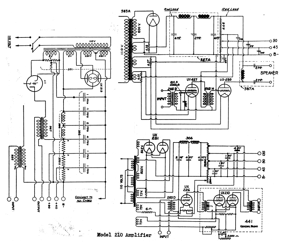
The schematic shows a valve / tube audio power amplifier and a type 390 Rectron B eliminator. The presented schematic illustrates a valve or tube audio power amplifier, which utilizes vacuum tubes to amplify audio signals. This type of amplifier...
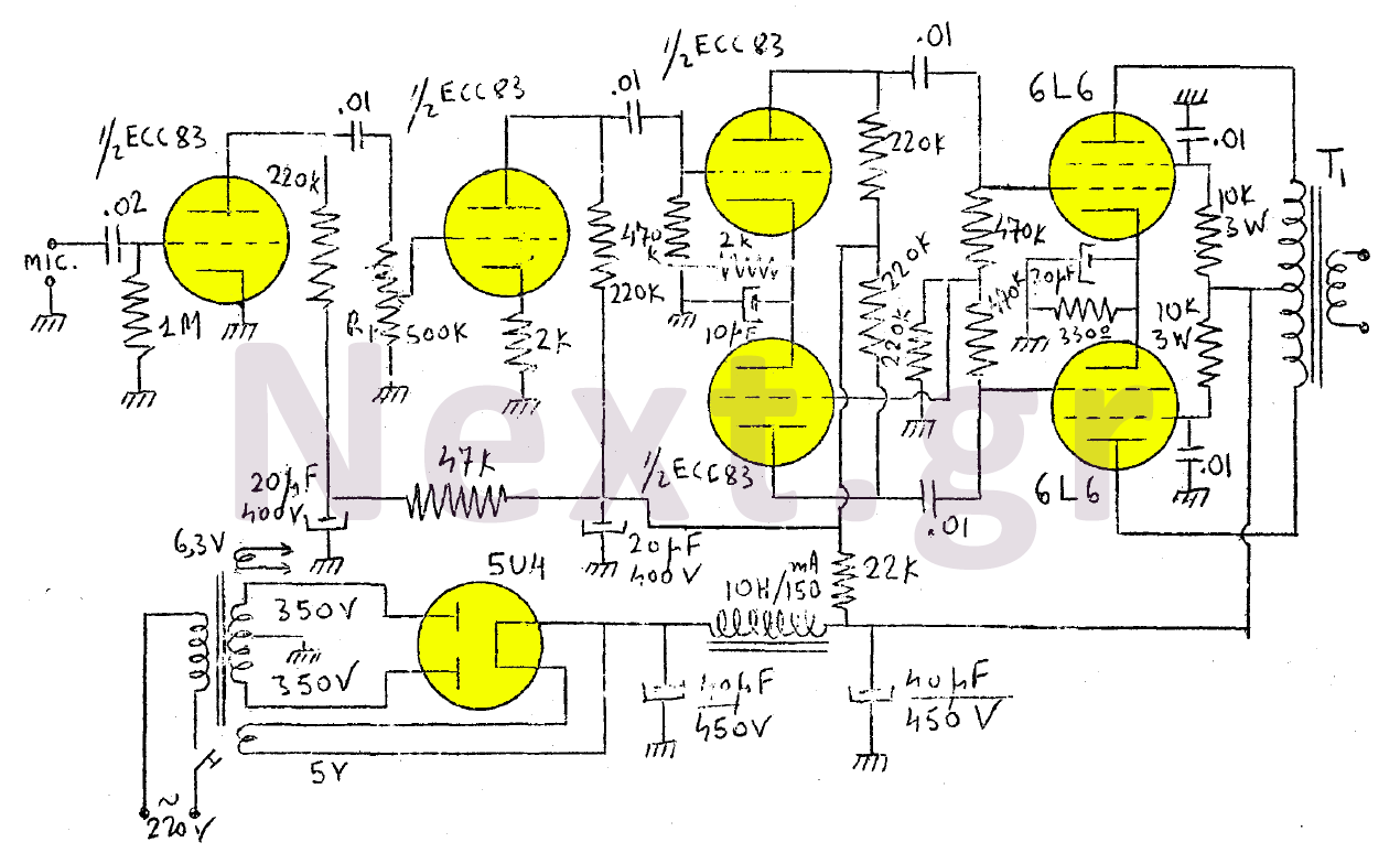
The amplifier in this design is rated at 30 Watts and is intended for use with a microphone. It is compatible with a crystal microphone and can be utilized for speeches, lectures, as a transmitter modulator, and in applications...
This is a successful vacuum tube project featuring a small amplifier where a 6V6GT output pentode is connected in triode mode, producing an output of approximately 4.5 watts. The project includes a single-ended audio amplifier with a resistive input...
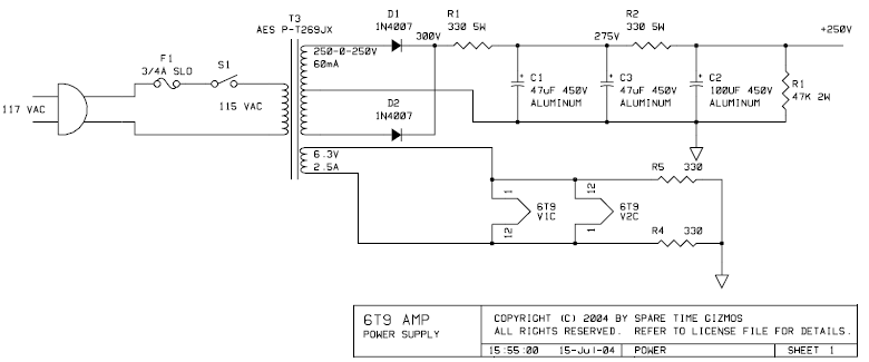
The PCB for this amplifier can be purchased from Spare Time Gizmos for $16 US. In a single afternoon, the entire board can be assembled and placed into a chassis of choice. The value and type of components are...
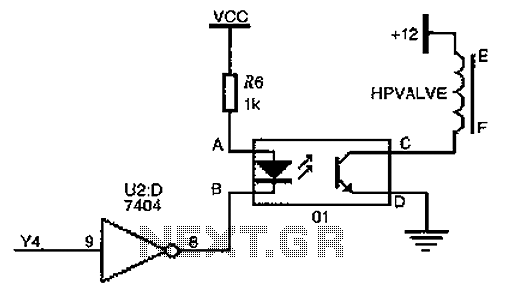
The driver circuit for the high-pressure natural gas shut-off valve utilizes solid-state relays. In dual-fuel mode operation, the fuel switching mechanism is controlled by a logic section that activates Y4 to a high state via U2 (7404 inverters). This...
.gif)
This article includes a list of references, but its sources remain unclear due to insufficient inline citations. More precise citations are needed to improve this article. Valves, also known as vacuum tubes, exhibit very high input impedance (nearly infinite...