
The General Electric XT-1-A AM transmitter
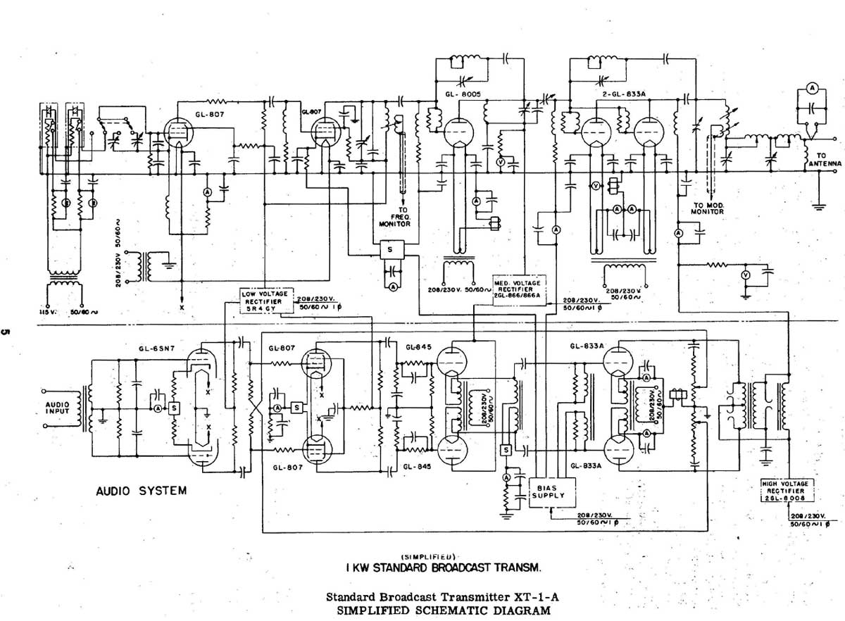
The GE BTA-25 transmitter is a notable piece of equipment in the history of AM broadcasting, characterized by its robust design and reliable performance. The transmitter employs the 833A triode, a high-power vacuum tube that is well-suited for radio frequency amplification. The 833A triode is known for its high gain and efficiency, making it an ideal choice for 1 kW AM transmitters. Its design eliminates the need for complex neutralization circuits, simplifying the overall transmitter architecture and enhancing reliability.
The tuning circuit of the GE BTA-25 is critical for maintaining optimal operating conditions and ensuring that the transmitter operates at the desired frequency. The presence of a mica capacitor within this circuit is essential for tuning stability and performance. Even when components fail, as evidenced by the blown capacitor incident, the resilience of the circuit can allow for continued operation, albeit potentially at reduced efficiency.
The construction quality of the GE BTA-25 is indicative of the manufacturing standards of the time, with a focus on durability and longevity. This transmitter was built to withstand the rigors of continuous operation, making it a preferred choice for many broadcasters. The production of the GE BTA-25 in Syracuse, NY, highlights the regional significance of electronics manufacturing during that period.
Overall, the GE BTA-25 transmitter represents a significant technological achievement in AM broadcasting, combining robust engineering with effective component selection to deliver reliable performance in various operational conditions.Back in the day when AM was king, no expense was spared on transmitting equipment. I remember the GE BTA-25 transmitter from the same era, it was build like a tank. Once, while we were repairing the Harris MW-50A main transmitter, the old GE burped, sputtered and threw an IPA overload, then returned to air. I looked in the IPA cabinet and found a mica capacitor had been blown in half. It was in the tuning circuit, but apparently there was still enough capacitance in the circuit for the transmitter to keep running. Like other 1 KW AM transmitter designs, this unit uses the venerable 833A triode. There are some advantages of this tube, as extra circuits for PA stage neutralization are not needed.
The full sales brochure can be found here (medium sized. pdf). These were manufactured in Syracuse, NY. 🔗 External reference
Related Circuits
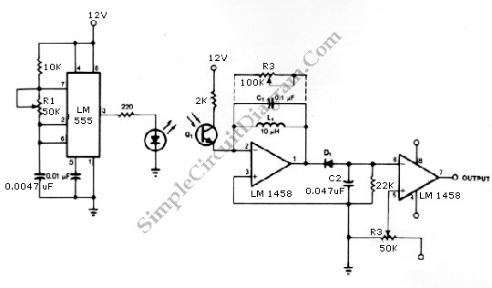
The infrared transmitter and receiver circuit depicted in the schematic diagram can function as a remote control. The transmitter operates as an oscillator circuit, with the frequency adjustable via the R1 potentiometer (or trimmer pot). This oscillation ensures that...
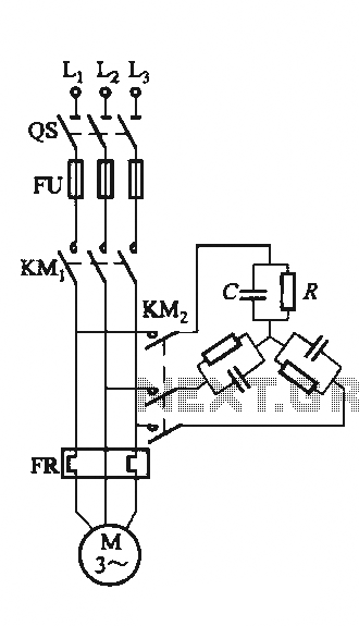
The circuit illustrated in Figure 3-151 consists of capacitor banks arranged in a specific configuration. Figure 3-151 (a) depicts capacitor banks connected in a shaped configuration, which is suitable for shaped or Y-connected motors. Figure 3-151 (b) shows Y-connected...
The core component of the circuit is a Colpitts type oscillator. The capacitors C3, C4, C5, C6, diodes CD1-CD2, and inductor L1 determine the oscillation frequency. The active components in the oscillator include the BF982 and a dual-gate MOSFET....
This circuit is a basic design that includes indicator LEDs and appropriate resistor values. A dotted line indicates that the IR LED is connected to the circuit via a length of wire (in this case, a telephone cable). The...

This FM transmitter has a number of features, with a volume control to adjust the input level and a small, neat box to make it easier to attach to a guitar. The volume control is positioned at the end...
Small Radio Transmitter. This article contains information about building a small radio transmitter, which has a PCB measuring 1.75 x 2.5 inches (45 mm x 68 mm) and offers a range of approximately 30 yards. The small radio transmitter is...