
The R2 Single Sideband Direct Conversion Receiver
The described audio preamp circuit utilizes advanced design techniques to minimize noise and improve performance. The transition from a common-base configuration to a common-emitter setup significantly enhances the noise figure, making it suitable for sensitive audio applications. The choice of using paralleled 2N4401 transistors is a strategic one, as it effectively lowers the noise performance at the desired input impedance, which is crucial for compatibility with the mixer stage.
The implementation of a diplexer serves to filter unwanted frequencies, with careful attention given to the design parameters such as the low-pass and high-pass cutoff frequencies. This allows for better control over the audio signal, ensuring that only the desired frequencies pass through while attenuating others that could introduce noise or distortion.
Custom inductors wound on potcores demonstrate a practical approach to achieving the necessary inductance while managing series resistance effectively. The use of low-capacitance inductors is vital for maintaining signal integrity, particularly in high-frequency applications.
The design also incorporates precision components, emphasizing the importance of matching and tolerances in achieving optimal performance. The decision to use low-noise operational amplifiers, such as the LM837 and MC33079P, further enhances the overall noise performance of the preamp stage.
The careful layout of the circuit and the addition of feedback capacitors to mitigate oscillations reflect a thorough understanding of high-frequency circuit behavior. The implementation of a quadrature generator for precise tuning of the phasing trimpots demonstrates a commitment to achieving high-performance audio processing.
Overall, the described circuit represents a sophisticated approach to audio preamplification, combining innovative design elements with practical engineering solutions to achieve low noise and high fidelity in audio applications.The old common-base audio preamp, having a noise figure of 5dB is an obvious target to improve the noise figure. A common-emitter configuration, with shunt feedback gives 50 ohms input resistance (preferred by the mixer) and a 2dB noise figure.
Two paralleled 2N4401 transistors results in better noise performance at such a low input impedance. A g ain of 60 masks most of the noise in the op-amp phase shifter that follows. Common collector ouput stages provide a low output impedance needed to drive the audio phase shifter. A simpler diplexer between mixer and preamp shaves a little off the noise figure too. Rick`s R2 diplexer has steeper stopband slope, but about 2dB loss. The TOKO 10RB inductors simply have too much series resistance: I wound my own on small potcores, 14x8 mm.
The potcore bobbins are very easy to wind, but its tricky to get the inductance exact - too much pressure from a mounting screw can change inductance dramatically. Potcore mounting hardware from the manufacturer is recommended. The 1. 2mH inductor should have low internal capacitance - 35 turns #32 wire in a single layer on a FT37-77 ferrite toroid.
Diplexer low-pass frequency at 6700 Hz. , and high-pass frequency at 170 Hz are outside the audio passband (350 - 3500 Hz. ). This means that unwanted phase shifts from mismatched diplexer parts are less troublesome, relaxing the need for extremely accurate component values. With the tuning method described below, some of the bad effects of mismatched components can be tuned out.
Nevertheless, diplexer components were matched with the aid of a commercial Maxwell impedance bridge. The phasing R`s and C`s were all scaled so that resistor values were much smaller. Otherwise, the Johnson noise from those warm, large value resistors adds so much noise that preamp gain would have to be much higher to achieve the same noise figure.
A return to a low- noise bipolar op-amp (LM837) gives lower noise than the FET-input TL074 with these lower resistor values. The Motorola MC33079P should work equally well. Most low-noise op-amps have extended frequency response as a side-effect. My circuit layout was slightly unstable, oscillating at 3 Mhz. Running at low power supply voltage doesn`t help, but oscillations are most likely caused by too much stray capacitance between the inputs and ground.
A 10pF feedback capacitor is usually enough to correct the problem, and doesn`t add noticeable phase error. A simpler USB/LSB sideband switching arrangement means a few less op-amps. This phasing circuit is capable of high sideband suppression; a minimum of 58 dB (figure 1). As Rick has mentioned, actually doing this well is very very difficult, mostly because of component tolerances.
Capacitors C24, C25, C26, C27, C28, C30 should all be of the same type. The Panasonic P-Series (polypropylene) capacitors have tight tolerance, and good temperature stability. Philips 460 series are even better, but unavailable in the larger sizes. Polystyrene capacitors are good too, but only small values are available. Almost all the resistors should be 1% precision resistors. Trimming these components is considered by many to be too difficult, partly because of the need for a quadrature signal generator.
I`m a believer in building your own test equipment; a very simple and accurate quadrature generator was developed that uses two common CMOS chips. This circuit can be built temporarily on a protoboard to trim the three phasing trimpots R43, R47, and R51 for best alternate sideband suppression.
The signal generator must supply two signals of the same frequency, same amplitude, but with exactly a 90 degree phase relationship. Since each of the three trimpots to be tuned affects some audio frequencies more than others, these two signals must be frequency agile: 300 - 4000 Hz.
Two square waves in quadrature are easily generated with a logic shift register. However, the harmonics of those squar 🔗 External reference
Related Circuits
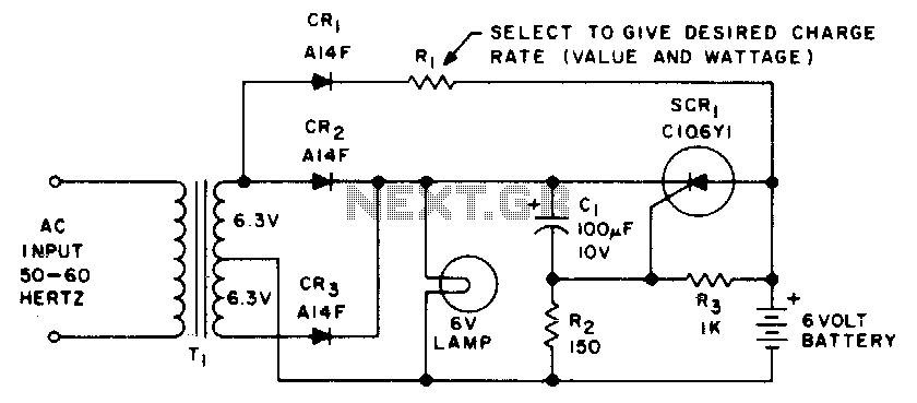
This emergency lighting system maintains a 6-volt battery at full charge and automatically switches from the AC supply to the battery. The emergency lighting system is designed to ensure reliable illumination during power outages or failures. It consists of a...
Most telephone equipment today utilizes a DTMF receiver integrated circuit (IC). A widely used DTMF receiver IC is the Motorola MT8870, which is commonly found in electronic communication circuits. The MT8870 is an 18-pin IC employed in telephones and...
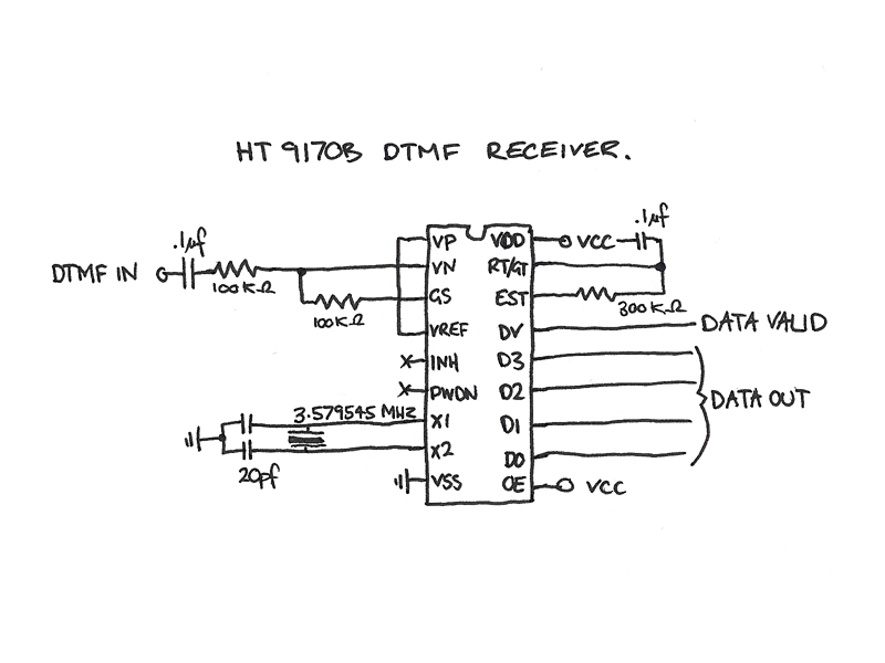
The four data lines from the Keypad Interface connect directly to the data inputs of the Holtek 9200B DTMF Generator (pins 6, 7, 8, and 9). The Inverted Chip Enable output from the Keypad Interface is connected to the...
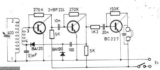
Oscillating circuits (coils) are constructed on a ferrite bar. For long wave reception, winding "1-2" consists of 135 turns, while winding "3-4" consists of 20 turns. For medium wave reception, winding "1-2" has 75 turns, and winding "3-4" has...
A current differencing transconductance amplifier (CDTA) serves as an active component that can be utilized to create various filter responses. The selection of different filter characteristics is achieved by altering the bias current supplied to the amplifier. The current differencing...
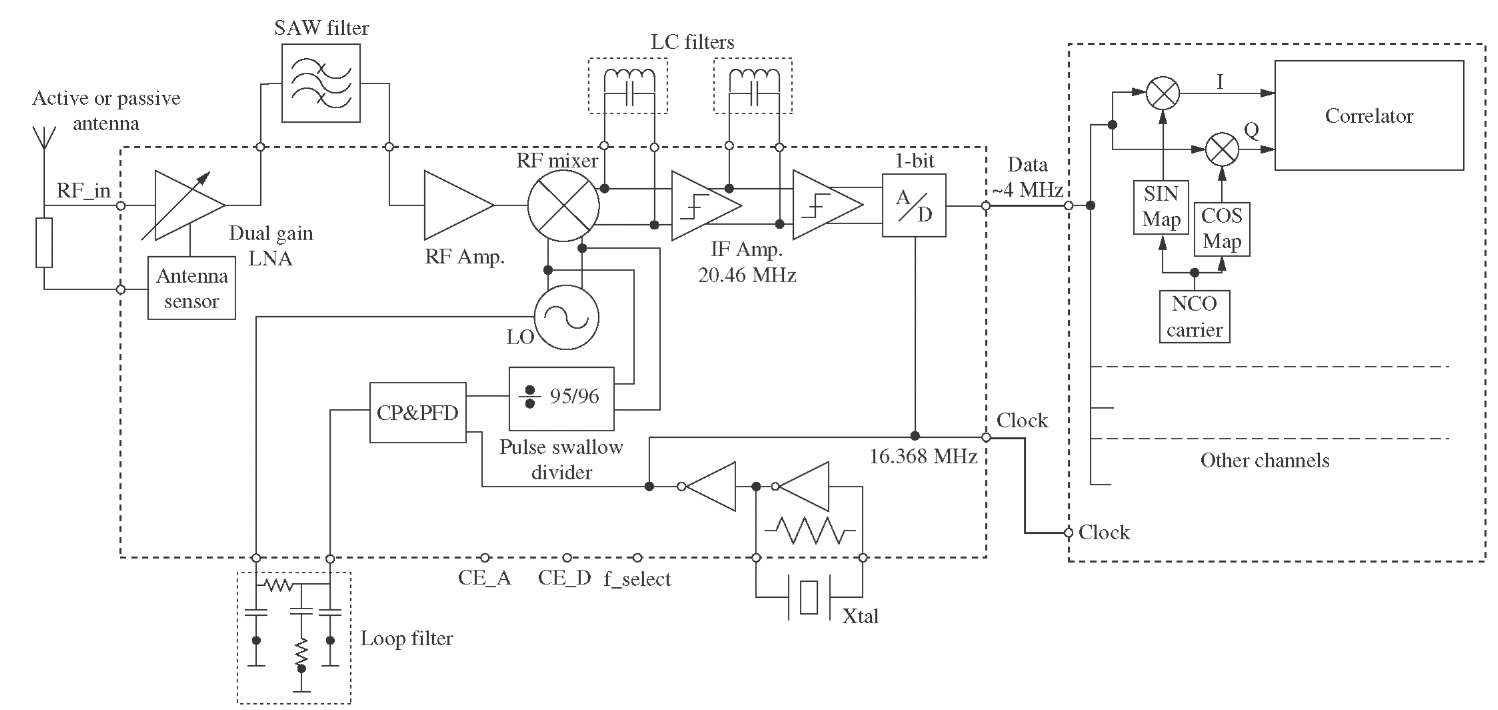
This topic will detail the design of each block of the radio frequency (RF) front-end, taking into account the technical requirements outlined previously. The design aims to meet specific specifications. The RF front-end is a critical component in communication systems,...