
The worlds smallest pong game

The µPONG circuit design showcases an innovative approach to recreating a classic gaming experience using minimal components. The core of the design lies in the utilization of an 8-pin PIC microcontroller, which not only reduces the footprint but also simplifies the overall complexity of the circuit. The integration of software delays in lieu of hardware one-shot timers exemplifies modern programming techniques in embedded systems, allowing for greater flexibility and efficiency in timing control.
The two potentiometers employed for bat control provide a user-friendly interface that closely resembles the original PONG game, enhancing the nostalgic experience for users. The circuit diagram illustrates the connections between the PIC microcontroller and the associated components, including the resistors that play a crucial role in video signal generation. The choice of resistors R1 and R2 is critical, as they must be selected to ensure the correct voltage levels are output to the television.
The use of a single I/O pin to produce a composite video signal is particularly noteworthy. This design decision maximizes the available resources of the microcontroller while overcoming the limitation of having a single output for video and synchronization. The translation of the GP0 pin states into a valid video signal demonstrates a clever use of electrical engineering principles, specifically in signal processing and impedance matching.
In conclusion, the µPONG project is an exemplary demonstration of how modern microcontroller technology can be leveraged to recreate classic electronics in a compact form factor. The design not only highlights the ingenuity of its creator but also serves as an educational reference for those interested in microcontroller programming, circuit design, and vintage gaming technology. The availability of the assembler source code provides an opportunity for further exploration and experimentation, allowing enthusiasts to modify and enhance the design as desired.a miniature version of the classic PONG game. The PONG game was invented back in 1966 by Ralph Baer [1, 2]. In the seventies the game became very popular and I remember that as a child I was completely fascinated by it. We had a later version at home, and on inspection it appeared that there was only one 40 pen IC in it, how did they do it In 197
3 the Dutch electronics magazine Elektuur (Elektor for the rest of the world) organized a circuit design contest. Electronics enthusiasts where invited to submit their favorite circuit designs. Via a complicated set of rules, which I have never understood, a calculation of the costs for the components that were used was made.
Part of the sum was given to the designer, the rest was given to the charity fund: "Aktion Sorgenkind". The first price was a homebrew version of PONG by the youthful B Lübcke from Kiel, Germany [3]! With nine TTL 74121 type one-shots and a handful of logic gates the clever designer was able to make a real functional tennis game on the TV.
I was amazed how simple it all could be! The µPONG game works essentially the same as the original 1966 design. However, in the PIC version the hardware one-shots have been replaced by software delays. A number of microcontroller based PONG games have been published or posted on the internet [4, 5]. This µPONG version is so far the smallest, using only an 8 pin PIC processor, and is the only one to use two potentiometers for the bat controls, just as the original PONG game. In Fig. 1 the circuit diagram of the µPONG is given. Although the circuit is pretty simple, it does contain some special tricks which will be explained in the text below.
Obviously the µPONG program contains many elements from the µSCOPE program. The line dispatcher concept is directly copied from the µSCOPE as well as the implementation of the asynchronous part and the routines that display the characters. If you are interested in finding out how the µPONG program works, the µSCOPE page will be a good start.
Some of the special tricks and features of the µPONG program will be explained on this page. I admit it, the µPONG program is not one of my finest pieces of programming. Nevertheless, the assembler source is available for downloading. Unfortunately it is not so well documented as the µSCOPE source. Sorry, this is a PAL only version! I do not think I will make an NTSC as well. This one has given me enough headaches already. It is time for something different now. For the generation of the video signal commonly 2 outputs are used. One for the video signal and one for the synchronization pulses. The µPONG project almost found a premature end when I discovered that I was short of one output. Of the 8 pins from the 12f675, 2 pins are needed for power, 2 pins are connected to the crystal and 2 pins are used to read out the potentiometers. This leaves 2 pins. To my surprise I learned from the datasheet that pin 4 (GP3) can only be used as a digital input. This leaves just one general purpose I/O pin that can be configured as output. Fortunately, this one I/O pin represents more than 1 bit! When the pin is configured as an output it exactly represents one bit (high or low). But it can have a third state namely high impedance or input. So each I/O in reality represents 1. 5 bit! A small circuit translates the three states of GP0 (low, high and high impedance) into a valid composite video signal.
To understand how it works, we will build the circuit up step by step. We start with two resistors connected as indicated in Fig. 2. With these kind of circuits it is important to realize that the video input of the television set has a termination resistance of 75 ohm to ground. By proper choice of R1 and R2 it is possible to translate +5V on the GP3 to 1. 0 V on the video input (white) and the high impedance state to 0. 3V (black). However, 0V on GP3 will not result in 0V on the video input (sync. level 🔗 External reference
Related Circuits

The circuit activates a light corresponding to the first button pressed in a "Who's First" game. Three stages are illustrated, but the circuit can be expanded to accommodate any number of buttons and lamps. The described circuit operates as a...

This is a design for a scoring game circuit suitable for any occasion where dice are used. The circuit utilizes a NE555 timer, a 74LS192 counter, a 74LS247 decoder, and a seven-segment LED display. The timer IC1 generates a...
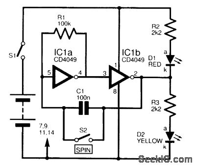
This circuit is designed to electronically simulate the tossing of a coin using a 4049 hex inverter integrated circuit (IC). It employs two of these ICs, specifically IC1a and IC1b, which are configured as an astable oscillator. This configuration...
This electronic game simulates a one-arm bandit game, appealing to electronics hobbyists. When toggle switch S1 is in the 'run' position, all segments of the 7-segment displays (DIS1 through DIS3) illuminate. Upon switching S1 from 'run' to 'stop', the...
This electronic game pits a human player against the machine. The opponents use a common game token and take turns moving along a path by one, two, or three steps, with the winner being the first to reach the...
The game-scoring display screen circuit diagram is depicted in the image above. The circuit consists of an add/subtract scoring input circuit, an add/subtract scoring circuit, a counting-decoding display circuit, and a reset circuit. The game-scoring display circuit is designed to...