
Timers for Rocket Ejection
The described circuit functions primarily as a timing mechanism for model rockets, utilizing various methods for circuit interruption to initiate a countdown timer upon launch. The initial setup involves a thin wire connected to the altimeter, which, when pulled, breaks the circuit and triggers the timer. The design must consider various factors affecting reliability, such as the strength of the wire and the potential for unintended circuit closures due to vibration or contact between wires during flight.
Alternative methods include the use of solder that melts under exhaust heat, reed switches activated by magnets, and audio-type jacks that maintain circuit integrity until ejection. Each method has unique advantages and drawbacks, particularly concerning durability and susceptibility to environmental factors like exhaust gases.
For more sophisticated implementations, integrating a g-switch provides an internal solution that senses the rocket's motion, allowing for a more streamlined design. The g-switch can be paired with a 556 dual-timer chip, which is ideal for applications requiring precise timing based on motion detection. The adjustable resistor allows for customization of the timing delay, providing flexibility for different rocket designs and launch conditions.
The selection of solid-state components such as MOSFETs over mechanical relays enhances the reliability of the timer circuit, reducing the risk of false triggering from mechanical vibrations. The overall assembly of the circuit can be achieved through various methods, whether by sourcing individual components or utilizing pre-manufactured PCBs, ensuring that the final product meets the necessary specifications for reliable operation in a rocket launch environment.This can be a thin strand of wire, like one of the copper "hairs" from a section of lamp cord, which is wired to the altimeter by terminals somewhere on the rocket body and anchored to the launch stand at some point. Rocket takes off, stand holds the wire back. Wire breaks, circuit is interrupted, and timer starts timing. Possible downside: Too strong a wire could hold a small rocket back. Dangling wires could contact each other in flight, restarting the countdown and making for late ejection. b. I`ve heard of those that ran the current through a section of solder which went under the rocket nozzle.
Exhaust heat melts solder, provided that the solder stayed in place. Actually that much heat could melt copper almost as easily. c. Another is to put a reed switch in the rocket, and have a magnet on the launch rod hold it closed. Rocket leaves rod, switch opens, timer starts timing. d. Some folks mount an audio-type earphone jack in the tail end of the rocket, facing down. A tethered plug is inserted in the jack, keeping the circuit closed. The plug is tied to the launch stand, so that when the rocket takes off, the plug is jerked out, the circuit broken, and the timer starts counting down. Possible downside: these jacks are not designed for high acceleration, so their reliability under rocket conditions must be monitored.
Also, exhaust products are corrosive, and may cause flaky connections with any electrical connector mounted near the motor. e. Terminals on the side of the rocket are connected with a strong wire by small alligator clips, like those used for Estes ignitors.
Wire is mounted firmly to test stand, so that when rocket takes off, the wire stays behind - clips slip off the terminals, breaking connection and starting the timer. Obviously, the rocket needs some kind of on/off switch mounted where it can be actuated on the pad. The timer is kept OFF until the last minute, switched on just before you walk back to the launch control area.
There are several other alternatives, no doubt some of them already occur to you. But the downside of the break-wire is that it requires something external to the rocket. . This is an internal switch that senses the motion of the rocket to trigger the timer. G-switches can be mounted on the circuit board, so that everything is inside the rocket. One can buy such switches - Perfectflite (listed below) has one for $8. Many rocketeers will take a common micro-switch, epoxy a weight to the lever, and orient it in the rocket so that when the rocket takes off, the lever closes the circuit, starting the timer. The g-switch is more often used withthe 556 dual-timer chip. This chip allows a single "pulse" or momentary circuit closure to start the timer sequence going. Possible downside: Dropping the rocket, or moving it abruptly, could start a g-switch timer counting down.
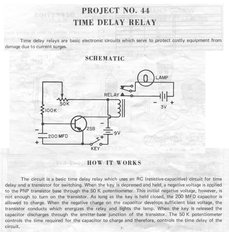
The more sophisticated timers often have internal protection against such events, but caution is still advised. 3. One of the resistors (50K) is adjustable (potentiometer) allowing user to change the rate at which the capacitor fills, thus adjusting the length of the delay.
4. Transistor (2SB) "reads" the the voltage in the capacitor, and when it reaches a certain (trigger) voltage, "opens the gates" and lets the current flow freely. (1) Use of a relay is not recommended in rocketry timers. The relay is a mechanical device that could be actuated by acceleration, heavy vibration, or rough handling.
A solid-state device such asMOSFET (Metal-Oxide Semiconductor Field Effect Transistor) should be used instead. 1. Get the parts yourself, figure out how they go together from the schematic and diagrams, and put it together with either an electronics project board, or by making the printed-circuit board yourself.
Kits for etching your own PC boards are available at Radio Shack and other electronics suppliers. 2. Buy the printed circuit board from Johnny, and get the part 🔗 External reference
Related Circuits
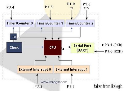
The diagram below illustrates a simplified representation of the main peripherals present in the 89S52 microcontroller, which is part of the 8052/8051 family. The 89S52 includes three Timers/Counters. The term "Timer/Counter" is applicable because this unit can function either...

This is a programmable clock timer circuit that utilizes individual LEDs to indicate hours and minutes. Twelve LEDs are arranged in a circle to represent the 12 hours of a clock face, while an additional 12 LEDs are positioned...
Eight LEDs are used to indicate the pad currently selected. These LEDs are connected to a decade counter, which sequences the LEDs when it receives a clock pulse. Only one LED can be lit at a time from the...
The objective of this circuit is to power a lamp or other device for a predetermined duration (30 minutes in this instance) and subsequently turn it off. This functionality is particularly beneficial for reading in bed at night, as...
The 16F84 has 13 outputs. All 13 can serve as inputs, but only 12 are normal outputs, one is an open-drain. An open-drain output has no active pull up - you have to provide an external (passive) pull up....
This launch controller can be used with low voltage battery igniters, which fire rocket engines in model rockets such as the Estes range. These circuits are electrical, only switches and contacts are involved. First the circuit for a single...
Warning: include(partials/cookie-banner.php): Failed to open stream: Permission denied in /var/www/html/nextgr/view-circuit.php on line 713
Warning: include(): Failed opening 'partials/cookie-banner.php' for inclusion (include_path='.:/usr/share/php') in /var/www/html/nextgr/view-circuit.php on line 713