
Acoustic Tone indicator
Part List
R1 = 68kΩ C1 = 2.2µF 16V D1 = 1N4148
R2 = 1.2kΩ C2-4 = 100nF 100V Q1 = BC550
R3 = 4.7kΩ C3 = 47µF 16V LSP = 8Ω 0.25W Loudspeaker
R4 = 100Ω IC1 = 7400 S1 = 1X2 mini Switch
TR1 = 1kΩ trimmer IC2 = 74121 All resistors are 1/4W 1% or 5%
The circuit described operates as a sound generator triggered by a short vibration at the input. It employs a monostable multivibrator configuration using a Schmitt trigger, which ensures reliable switching characteristics and noise immunity. The output of the monostable multivibrator is connected to a TTL oscillator (IC2, 74121), which generates a square wave signal at a frequency of 2kHz.
The circuit begins when a short input pulse is applied, causing the monostable to produce a pulse of approximately 100ms. This pulse activates the oscillator, which then produces a continuous square wave output at the specified frequency. The loudspeaker or piezoelectric element (LSP) is driven by this oscillating signal, producing an audible sound.
The circuit design includes a switch (S1) that allows for the selection of the input polarity, providing flexibility in how the circuit responds to different types of input signals. The frequency of the generated sound can be adjusted by changing the values of capacitor C4 or resistor R2, which influences the timing characteristics of the oscillator.
The trimmer resistor (TR1) is used to fine-tune the output level of the loudspeaker, allowing for control over the volume of the sound produced. The power supply of +5V is sufficient for the operation of the TTL logic components and the sound output device.
In summary, this circuit serves as a basic sound generation system, responsive to input vibrations, and is configurable for various sound frequencies and output levels. This makes it suitable for applications requiring acoustic signaling or alerts based on mechanical vibrations.With this circuit, we can have a acoustic clue, frequency 2KHZ, when we have a short vibration in his entry. It is constituted from monostable multivibritor (with schmitt trigger inputs), with duration roughly 100msec, oscillator TTL, that oscillating in their 2KHZ and one rung of expense a loudspeaker or piezoelectric element.
The square vibration that is applied in his entry, trigger his multivibritor that with line drive the oscillator and his the loudspeaker. With switch S1, we can select the polarity of vibration of entry, if this is positive or negative. The frequency of oscillator can change, if we change the capacitor C4 or resistance R2, so that changes also the frequency of sound that we hear from the loudspeaker and with the TR1 we alter the intensity of him tone in the loudspeaker.
The power supply is + 5V. Part List R1= 68Kohms C1= 2.2uF 16V D1= 1N4148 R2= 1.2Kohms C2-4= 100nF 100V Q1= BC550 R3= 4.7Kohms C3= 47uF 16V LSP= 8ohms 0W25 Loudspeaker R4=100ohms IC1= 7400 S1= 1X2 mini Switch TR1= 1Kohms trimmer IC2= 74121 All Resistors is 1/4W 1% or 5% 🔗 External reference
Related Circuits

The sensitivity of the circuit can be adjusted using potentiometer P1 to avoid responding to ambient noise levels. Diodes D1 and D2 rectify the signal, while capacitor C4 provides smoothing. When the voltage across C4 exceeds 0.5 V, transistor...
The paraphase configuration is noteworthy for its ability to adjust either treble or bass, but not both simultaneously. The adjustments made to the tone controls directly influence the slope of the frequency response and the extent of bass and...
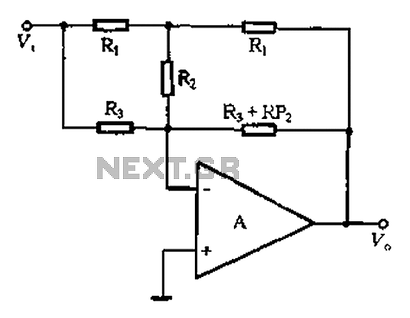
At high frequencies, the capacitor Cz can be considered a short circuit (i.e., the resistance of the RPi is negligible). This is illustrated in Figure 4-6 (a) of the apparatus, which corresponds to the equivalent circuit shown in Figure...
The circuit illustrated produces a brief sequence of rapidly alternating tones, reminiscent of the sounds associated with advanced computers, often featured in science fiction. This circuit was designed for the composition "Be Quite Still" by the band "The Cassettes."...
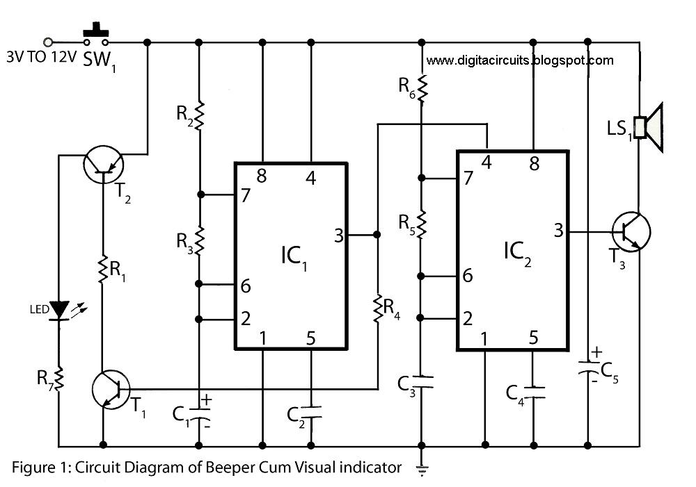
This circuit of a beeper and visual indicator is constructed using two timer integrated circuits (ICs) configured in an astable multivibrator mode. The frequency produced by IC1 is regulated by capacitor C1. The output from pin 3 of IC1...
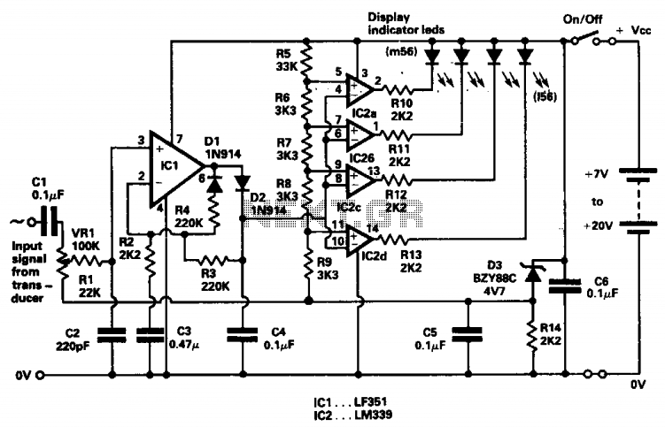
The indicator was designed to display the peak level of small AC signals from various transducers, including microphones, strain gauges, and photodiodes. The circuit responds to input signals within the audio frequency spectrum, specifically from 30 Hz to 20...