
Transistor based 3.3V-5V Level Translator
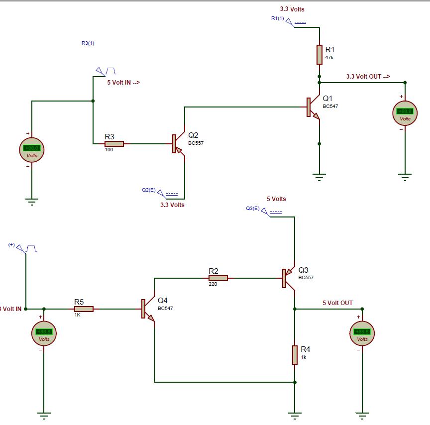
The circuit for voltage level translation between a 3.3V device and a 5V microcontroller typically employs a simple transistor switch configuration. The primary components include an NPN transistor, resistors, and the two devices that need to communicate.
In this setup, the 5V microcontroller sends a high signal (5V) to the base of the NPN transistor through a current-limiting resistor. This turns the transistor on, allowing current to flow from the collector to the emitter. The collector is connected to the 3.3V device's input pin, while the emitter is connected to ground. When the transistor is activated, it effectively pulls the 3.3V device's input to ground, representing a low signal.
Conversely, when the microcontroller sends a low signal (0V), the transistor is turned off, and the input pin of the 3.3V device is pulled high via a pull-up resistor connected to the 3.3V supply. This configuration ensures that the 3.3V device receives the correct voltage levels corresponding to the signals from the 5V microcontroller.
For a complete implementation, it is crucial to select appropriate resistor values to ensure proper current flow and to prevent damage to the components. The pull-up resistor value should be chosen based on the input characteristics of the 3.3V device to ensure reliable operation. The schematic can be simulated in Proteus, allowing for verification of the functionality before physical implementation.
This level-shifting method is commonly used in various applications where different voltage levels need to communicate effectively, ensuring compatibility and reliable data transfer between components operating at different voltages.Nowadays most of the devices are running on 3.3 volts, and likewise their communication levels also work on 3.3 volts. For example XBee runs on 3.3 volts and to interface it with microcontrollers running on 5V, one needs to translated voltages levels so that they both communicate.
This post gives a schematic of transistor based level translation with Proetus simulation 🔗 External reference
Related Circuits
The addition of a mono microphone-level output to the 302 is a beneficial enhancement for connecting transcription recorders, Comtek transmitters, and other inputs. The accompanying diagram demonstrates the correct wiring to create a mono microphone-level output from the tape...
The following circuit illustrates a Mains Remote-Alert Circuit Diagram. Features include simple circuitry, with the transmitted signal being conveyed effectively. The Mains Remote-Alert Circuit is designed to provide a notification system that alerts users about the status of mains power....
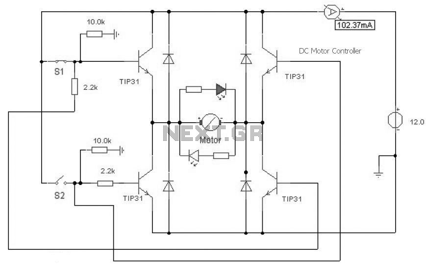
This is a DC motor controller circuit built using a TIP31 transistor based on the H-Bridge concept. The switches S1 and S2 are normally open, push-to-close buttons. The LED serves to indicate the direction of motor rotation. The described DC...
This circuit was designed to provide a valuable test equipment tool for sound reinforcement systems like guitar amplifiers and the like. Used in conjunction with a signal generator it can be of considerable help in setting and controlling levels...
This is a hot water level indicator circuit. This circuit can be used to monitor the level of hot water in a tank. It is simple and inexpensive. The hot water level indicator circuit is designed to provide a reliable...
A micro power supply unit (PSU) is designed to power a breadboard with a voltage output of 5 volts. It can be connected to a 9V battery, a 12V source, or any other direct current (DC) power supply ranging...