
Triangular Wave Generator

The triangular wave generator circuit typically employs an op-amp in an integrator configuration. The fundamental principle involves generating a square wave signal, which is then fed into the input of the integrator circuit. The op-amp integrates this square wave, producing a triangular wave output.
In the circuit, the op-amp is connected with feedback that includes a capacitor and a resistor. The square wave input is applied to the non-inverting terminal of the op-amp. The integration process occurs as the op-amp outputs a voltage that ramps up and down, corresponding to the square wave's high and low states. The output voltage increases linearly during the positive half-cycle of the square wave and decreases linearly during the negative half-cycle, resulting in a triangular waveform.
The frequency of the triangular wave is determined by the frequency of the input square wave and the RC time constant, which is defined by the resistor and capacitor values in the feedback loop. Adjusting these components allows for the tuning of the triangular wave's characteristics, including its amplitude and frequency.
To construct a practical triangular wave generator, a suitable op-amp such as the LM741 can be used. The circuit should also include power supply decoupling for stability and noise reduction. The output can be further processed or utilized in various applications, such as waveform generation for signal processing, modulation, or testing purposes.
In summary, the triangular wave generator circuit based on an op-amp provides a reliable method for generating triangular waveforms through the integration of square wave signals, with practical applications across various electronic systems.Triangular wave generator using opamp. Circuit diagram theory and working. Integrating square wave produces a triangular wave. Practical circuit diagram of triangular wave generator.. 🔗 External reference
Related Circuits
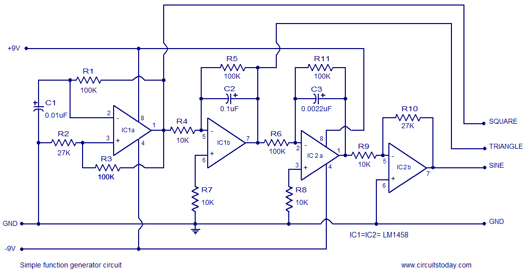
A simple function generator circuit utilizing the LM1458 is presented here. The LM1458 is a dual general-purpose operational amplifier. The two op-amps within the LM1458 share a common bias network and power supply line, yet operate independently. The function generator...
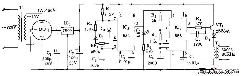
Adjust the RP1 to modify the pulse duty cycle of IC2, which in turn alters the pulse oscillation time of IC3. This regulation allows for the control of ozone generation time, effectively changing the concentration of ozone in the...

Generating sine waves with controlled frequencies over a wide range is challenging when using RC or LC sinusoidal oscillators. However, this can be effectively achieved using a wideband digital square wave oscillator, a counter, and a weighted summing network....
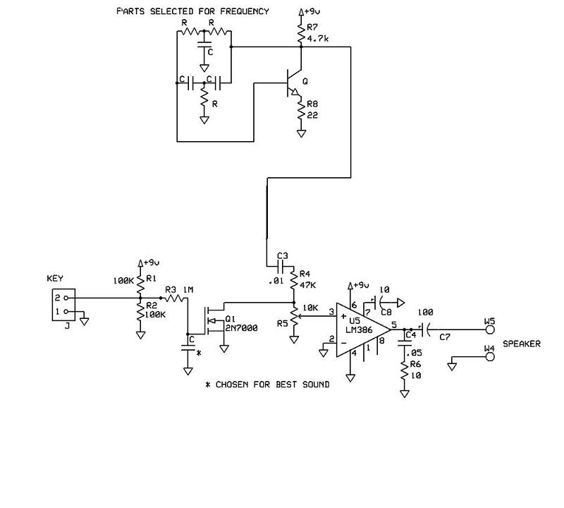
A schematic for a code practice oscillator is needed, which can be connected to a keyer. The desired setup involves using a Picokeyer, allowing the oscillator to be plugged into the key jack of the Picokeyer. The output should...
Three circuit options Can be synchronized to Christmas tree flashing lights This circuit generates a dual-tone bells ringing similar to most door-bell units. It can be used in many applications other than door-bell. In the Notes below several options...
This sine wave generator is adjustable between 15 Hz and 150 kHz. The circuit is essentially a Wien-bridge oscillator, featuring multiple capacitor selections. The sine wave generator operates on the principle of the Wien-bridge oscillator, which is known for producing...