
True rms detector

The described circuit functions as a true RMS converter, which is essential for measuring the effective value of varying AC signals in a DC format. The circuit's design typically incorporates a precision rectifier to ensure accurate representation of the input signal's RMS value. This rectifier is often followed by a low-pass filter, which smooths the output to provide a stable DC voltage that corresponds to the RMS value.
In terms of components, the circuit generally includes operational amplifiers configured for rectification, precision resistors for maintaining accuracy, and a filter capacitor that plays a crucial role in determining the lower frequency response. The size of the filter capacitor directly influences the cutoff frequency of the low-pass filter, with larger capacitors allowing for lower frequency signals to be processed effectively.
The operational amplifiers used in the circuit must have a high slew rate and bandwidth to accommodate the specified frequency range, especially since the circuit is capable of handling frequencies up to 500 kHz. Additionally, the choice of precision resistors is critical to maintain the stated accuracy of 2%, ensuring minimal error in the output voltage.
Overall, this circuit is particularly useful in applications where accurate RMS measurements of AC signals are required, such as in power monitoring systems, audio equipment, and various electronic testing environments. Its ability to handle both AC and DC inputs makes it versatile for a range of electronic applications.The circuit will provide a dc output equal to the rms value of the input. Accuracy is typically 2% for a 20 Vpp input signal from 50 Hz to 100 kHz, although it"s usable to about 500 kHz. The lower frequency is limited by the size of the filter capacitor Since the input is dc coupled, it can provide the true rms equivalent of a dc and ac signal.
Related Circuits
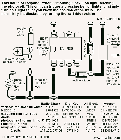
This photocell is best mounted at tie level between the rails. The variable resistor adjusts the sensitivity of the circuit. This circuit can be powered by either 6 or 12 volts - BE SURE to use the proper relay;...
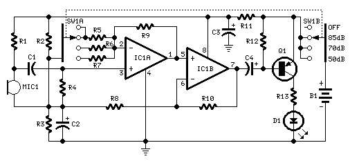
One LED monitors three levels: 50, 70 & 85 dB. Useful to detect too noisy environments. This circuit is intended to signal, through a flashing LED, the exceeding of a fixed threshold in room noise, chosen from three fixed...
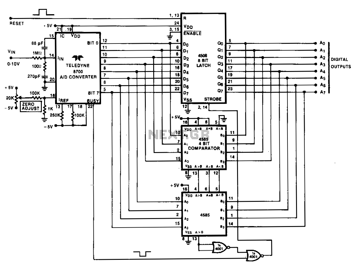
Analog peak detection is achieved by repeatedly measuring the input signal with an A/D converter and comparing the current reading with the previous reading. If the current reading is larger than the previous one, the current reading is stored...
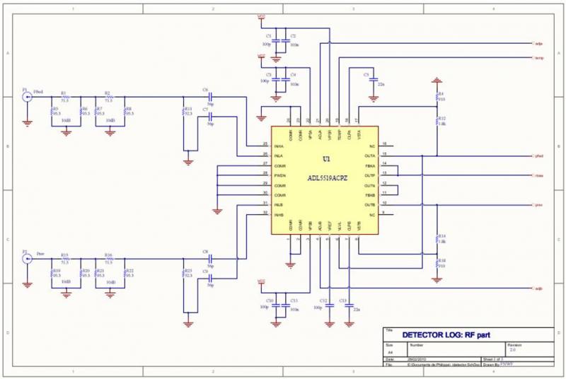
The ADL5519 is particularly focused on bandwidth, specified up to 8 GHz, though it remains usable at 10 GHz with reduced dynamic range. It features two channels, allowing for the measurement of power transmitted to the antenna and the...
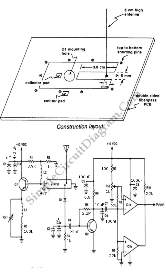
The UHF motion detector operates on the Doppler radar principle. An oscillating signal is generated by the oscillator (Q1), and a portion of this energy is reflected back. The UHF motion detector employs the Doppler radar principle to detect motion...
This is a straightforward liquid detector that utilizes a relay to activate an evacuation valve. It can be employed for water or any conductive liquid. The liquid detector circuit operates by leveraging the conductivity of liquids to trigger a relay....