
Tubes Headphone Amplifier
The power supply output network has one 1K-ohm/2W and two 1K-ohm/2W film resistors in parallel. You can trim the output voltage by adjusting the value of the second 1K-ohm/2W pair slightly up or down from 500 ohms.
The first version of the power supply used A.C. straight out of the transformer to heat the filaments. The amp sounded fine, but had a very loud hum that didn't go away until the filament circuit was rectified as shown in the schematic. To wire the tube sockets, I wanted a physical wiring guide. I printed a piece of paper with three copies of the tube pin layout and then penciled in the various connections. I tried several layouts until I found one I liked. Shown above (figure 5) is my wiring guide for an earlier version of the amplifier.
Once you have made all the holes, file down any rough edges. Test fit all the pieces. Drill pilot holes for the mounting screws. Test fit each component. Then, when everything fits, stop and paint the chassis and cover before mounting the hardware.
If you use the Hammond chassis in the parts list, it is already painted grey. I marked it up doing the layout for the parts, so I roughed it up with sandpaper and painted it. I used "American Accents Hunt Club Green Satin" by Rustoleum and do not especially recommend it, since it looks a bit like plain old olive drab. After painting, you really should let the paint dry for two days. Otherwise, it scrapes off easily. Once the amp is up and running, it gets warm enough to "bake" the paint somewhat, and you can smell the paint baking for the first week or two.
Once the paint is dry, mount the hardware. Use machine screws and nuts and do not forget the star-type lockwashers. (The fasteners are not on the parts list - I get this kind of small mechanical stuff from a local hardware store.) Do not use sheet metal screws to mount anything other than the cover, as you will be sorry in a year or two if you do. The heat/cooling cycle will loosen up the sheet metal screws eventually. Based on my experience, in the worst cases you can only tighten sheet metal screws down a few times before they start to get sloppy and refuse to tighten up any more. Also, they leave a sharp point exposed on the inside of the chassis. Put the tubes in the tube sockets. Do not put the bottom cover on yet. Prop the amp securely on its side so you can get at the wiring inside. If you have access to a Variac, use it to slowly bring the voltage up to line level. Otherwise, the fallback method is to stand back and turn it on. Once in a while electrolytic capacitors have been known to pop, and they can spit small amounts of hot gel when they go, so make sure your hands and eyes are several feet away and out of range. If nothing hisses, pops, splutters, or explodes you are halfway there.
The best way to test the high voltage supply is actually to power up the amp with the tubes in place; otherwise the power supply voltages climb up to 400v+ with no load, which doesn't really say much. To trim the high voltage supply, change the value(s) of the paralleled 1K, 2W resistors. These should probably be decreased to get the voltage up to around 350v. I doubt people are going to have problems with the output being much higher than that. Given the 6v tube-to-tube variation I observed, I would think anything between 340 and 360 volts should be fine. When I run the amp and watch it for 30 minutes or so, the high voltage supply drifts slowly up or down a volt or two, but the average is pretty close to 349 volts. Being a bass player and a drummer, I chose several of my favorite bass-player albums to use as test discs with my Denon DCM-370: "Outbound" HDCD by the Flecktones; Matthew Garrison's self-named CD, "Bent" by Gary Willis. The last also features monster drummer Dennis Chambers. The big difference between the earlier version of the 6N1P amp and this revised version is that the new version is capable of ear-splitting volumes driving the Sonys and the Senns, and also gets very loud with the K501s. The older version worked but only at polite volume levels.
There are much bigger differences between the three headphones than there are between the three amps. All three amps make the Sonys sound like Sonys and so forth. I didn't notice a lot of difference in sound field and imaging between the three amps, taking crossfeed into account as best I could. The CMoy/Hansen amp is a good standard of comparison, since lots of people have heard it by now. It has a typical solid-state sound: punchy and a little raspy in the upper midrange. At high volumes, the bass gets a little thin - it's still loud, but it loses some of its rounded character.
Whatever NAD put in the 314 headphone jack, it sounds surprisingly good. It has better octave-to-octave balance than the cmoy/Hansen, eg. a more even frequency response. At loud volumes the bass is smoother and rounder than the cmoy amp. The NAD (obviously) doesn't have crossfeed, though.
The 6N1P OTL stays smooth at high volumes, the treble is a bit more laid back than the solid state amps, but just a bit. The tube amp is just as punchy (a benefit of OTL) and the bass is very full and round, especially when using crossfeed. The amp has that tube "sweetness", but I have to say that the NAD sounds almost as "sweet", meaning a lack of harshness or "grain" in the sound. With the Meier crossfeed connected to the 6N1P OTL, the Senn HD565s have almost too much bass for my tastes, but without crossfeed they are just about right. Conversely, the AKGs sound a little thin without the crossfeed, but just right with it. For long listening sessions, I think the 6N1P amp, with crossfeed, with the K501s, is a very good sounding and low-ear-fatigue setup.
The amplifier is based on the Morgan Jones design, utilizing Svetlana 6N1P tubes, which are dual triodes. This configuration allows for enhanced audio performance due to the presence of two independent amplifiers within each tube. The amplifier's topology remains unchanged, with a focus on providing a robust power supply capable of meeting the demands of the 6N1P tubes, which require a higher filament current and plate voltage compared to other tube types such as the 6922. The design incorporates a Hammond 269AX transformer, which supplies the necessary voltages without using the center tap of the high voltage secondary winding to avoid potential issues.
The power supply circuit features a combination of resistors to stabilize and adjust the output voltage, ensuring that the amplifier operates within the desired voltage range of approximately 340 to 360 volts. The inclusion of a rectified filament circuit addresses the issue of hum commonly associated with AC filament heating, improving the overall sound quality of the amplifier.
The assembly process emphasizes careful component fitting and chassis preparation, including painting and hardware installation. The use of machine screws and lockwashers is recommended for durability, and precautions are advised during the initial power-up to avoid damage to components. Testing the amplifier under load conditions is crucial for accurate voltage readings and performance verification.
Overall, the 6N1P amplifier design provides a satisfying listening experience, characterized by smooth audio reproduction and effective handling of various headphone types, making it suitable for extended listening sessions.The amp is built according to the Morgan Jones design. In the spirit of DIY, I made a few modifications. I did not change the circuit topology at all, but used Svetlana 6N1P tubes, as noted. I also used a conventional power supply instead of the wall wart/filament transformer combination, because the 6N1P has a higher filament draw (2 amps) than 6922s, and I wanted plenty of high-voltage supply, too. If you can read an op-amp circuit diagram, you should be able to read this tube circuit with no trouble.
The 6N1P family are "dual triodes," each tube containing two separate amplifiers in the same device. Each triode has three circuit connections: a source of electrons ("cathode"), an output that receives the electron flow ("anode" or "plate"), and a "grid" which controls the flow. A separate wire filament (the orange glow in tubes) heats the cathode to make it give off electrons. The power supply shown for the original Morgan Jones amp is unusual and clever, but the 6N1Ps need a higher voltage for the plates and more current for the filament heaters than the original supply can produce. [Editor: The 6N1P needs a higher plate voltage than the 6922/6JD8 to reach its optimal operating range.] The heater current is 600mA for the 6N1P versus 365mA for the 6922, a significant difference.
The clever wall-wart scheme, which is barely adequate for the 6922s, clearly can't provide enough current for 6N1Ps. So I used a more traditional power supply. Tube amps traditionally have a power transformer that has a separate winding for the heater filaments in addition to the main winding.
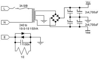
As it happens, a transformer is available that provides usable voltages for this project, the Hammond 269AX. Do not use the center tap (red/yellow) on the high voltage secondary winding of the 269AX. Also, be careful if you run this power supply for very long without a load on it, since voltages will quickly accumulate into the 400 volt range.
The amp will draw about 27 milliamps of current. If you want a dummy load to use when checking the power supply, you will need to cobble together a 13k ohm load capable of dispersing 10 watts. The power supply output network has one 1K-ohm/2W and two 1K-ohm/2W film resistors in parallel. You can trim the output voltage by adjusting the value of the second 1K-ohm/2W pair slightly up or down from 500 ohms.
The first version of the power supply used A.C. straight out of the transformer to heat the filaments. The amp sounded fine, but had a very loud hum that didn't go away until the filament circuit was rectified as shown in the schematic. To wire the tube sockets, I wanted a physical wiring guide. I printed a piece of paper with three copies of the tube pin layout and then penciled in the various connections.
I tried several layouts until I found one I liked. Shown above (figure 5) is my wiring guide for an earlier version of the amplifier. Once you have made all the holes, file down any rough edges. Test fit all the pieces. Drill pilot holes for the mounting screws. Test fit each component. Then, when everything fits, stop and paint the chassis and cover before mounting the hardware. If you use the Hammond chassis in the parts list, it is already painted grey. I marked it up doing the layout for the parts, so I roughed it up with sandpaper and painted it. I used "American Accents Hunt Club Green Satin" by Rustoleum and do not especially recommend it, since it looks a bit like plain old olive drab. After painting, you really should let the paint dry for two days. Otherwise, it scrapes off easily. Once the amp is up and running, it gets warm enough to "bake" the paint somewhat, and you can smell the paint baking for the first week or two.
Once the paint is dry, mount the hardware. Use machine screws and nuts and do not forget the star-type lockwashers. (The fasteners are not on the parts list - I get this kind of small mechanical stuff from a local hardware store.) Do not use sheet metal screws to mount anything other than the cover, as you will be sorry in a year or two if you do. The heat/cooling cycle will loosen up the sheet metal screws eventually. Based on my experience, in the worst cases you can only tighten sheet metal screws down a few times before they start to get sloppy and refuse to tighten up any more.
Also, they leave a sharp point exposed on the inside of the chassis. Put the tubes in the tube sockets. Do not put the bottom cover on yet. Prop the amp securely on its side so you can get at the wiring inside. If you have access to a Variac, use it to slowly bring the voltage up to line level. Otherwise, the fallback method is to stand back and turn it on. Once in a while electrolytic capacitors have been known to pop, and they can spit small amounts of hot gel when they go, so make sure your hands and eyes are several feet away and out of range. If nothing hisses, pops, splutters, or explodes you are halfway there. The best way to test the high voltage supply is actually to power up the amp with the tubes in place; otherwise the power supply voltages climb up to 400v+ with no load, which doesn't really say much.
To trim the high voltage supply, change the value(s) of the paralleled 1K, 2W resistors. These should probably be decreased to get the voltage up to around 350v. I doubt people are going to have problems with the output being much higher than that. Given the 6v tube-to-tube variation I observed, I would think anything between 340 and 360 volts should be fine. When I run the amp and watch it for 30 minutes or so, the high voltage supply drifts slowly up or down a volt or two, but the average is pretty close to 349 volts.
Being a bass player and a drummer, I chose several of my favorite bass-player albums to use as test discs with my Denon DCM-370: "Outbound" HDCD by the Flecktones; Matthew Garrison's self-named CD, "Bent" by Gary Willis. The last also features monster drummer Dennis Chambers. The big difference between the earlier version of the 6N1P amp and this revised version is that the new version is capable of ear-splitting volumes driving the Sonys and the Senns, and also gets very loud with the K501s.
The older version worked but only at polite volume levels. There are much bigger differences between the three headphones than there are between the three amps. All three amps make the Sonys sound like Sonys and so forth. I didn't notice a lot of difference in sound field and imaging between the three amps, taking crossfeed into account as best I could.
The CMoy/Hansen amp is a good standard of comparison, since lots of people have heard it by now. It has a typical solid-state sound: punchy and a little raspy in the upper midrange. At high volumes, the bass gets a little thin - it's still loud, but it loses some of its rounded character. Whatever NAD put in the 314 headphone jack, it sounds surprisingly good. It has better octave-to-octave balance than the cmoy/Hansen, eg. a more even frequency response. At loud volumes the bass is smoother and rounder than the cmoy amp. The NAD (obviously) doesn't have crossfeed, though. The 6N1P OTL stays smooth at high volumes, the treble is a bit more laid back than the solid state amps, but just a bit.
The tube amp is just as punchy (a benefit of OTL) and the bass is very full and round, especially when using crossfeed. The amp has that tube "sweetness", but I have to say that the NAD sounds almost as "sweet", meaning a lack of harshness or "grain" in the sound.
With the Meier crossfeed connected to the 6N1P OTL, the Senn HD565s have almost too much bass for my tastes, but without crossfeed they are just about right. Conversely, the AKGs sound a little thin without the crossfeed, but just right with it. For long listening sessions, I think the 6N1P amp, with crossfeed, with the K501s, is a very good sounding and low-ear-fatigue setup.
🔗 External reference
Related Circuits
This simple audio power amplifier was originally designed for a circuit board workshop conducted by the OSU IEEE Student Group. At the workshop, 20 participants each constructed this amplifier by etching and drilling the single-sided circuit board, soldering all...
This preamplifier amplifies the signal from a microphone, an amplifier so that it can be further strengthened. The circuit supplies an output signal line. With two transistors, it is not difficult to build such a circuit. The amplifier produces...
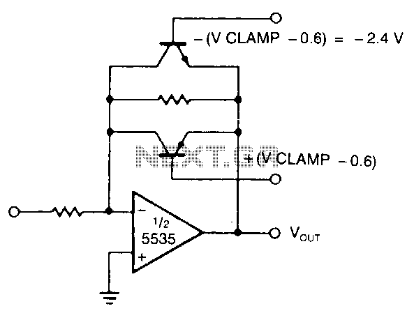
The modified inverting amplifier employs an active clamp to precisely limit the output swing. Consideration must be given to the VBE of the transistors. The output swing is restricted by the base-emitter breakdown of the transistors. A straightforward circuit...
A 30W Class AB power amplifier circuit diagram utilizes a power transistor. To set up the amplifier, adjust the variable resistor R1 to its maximum value and R12 to zero. After completing this setup, activate the amplifier. Adjust R1...
The NE5539 wideband operational amplifier can be easily configured as a color video amplifier. The gain remains stable, varying by less than 0.5% from the lowest to the highest state. The maximum differential phase shift is approximately +0.1. The...
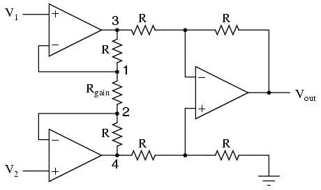
It is advantageous to adjust the gain of an amplifier circuit without modifying more than one resistor value, unlike the previous design of the differential amplifier. The instrumentation amplifier builds upon the last version of the differential amplifier to...