
TV Remote Control Jammer
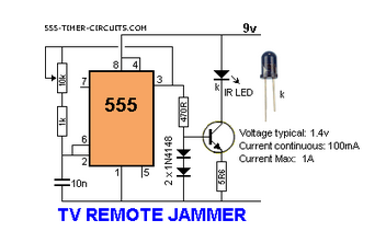
The circuit operates by generating a continuous infrared (IR) signal that mimics the signal typically sent by a remote control. This is achieved through the use of an infrared LED, which emits light in the infrared spectrum. The IR LED is driven by a simple oscillator circuit, which can be constructed using a 555 timer IC configured in astable mode.
In this configuration, the 555 timer produces a square wave output that toggles between high and low states at a specific frequency. The output of the timer is connected to the anode of the IR LED, while the cathode is connected to ground. A current-limiting resistor is placed in series with the LED to prevent excessive current flow, ensuring the LED operates within its specified limits.
The frequency of the oscillation can be adjusted by changing the values of the resistors and capacitors connected to the 555 timer. This allows for fine-tuning of the interference signal to ensure it effectively disrupts the communication between the remote control and the television. The circuit can be powered by a standard DC power supply, such as a 9V battery or an external power adapter.
When the circuit is activated, the IR LED continuously emits a modulated infrared signal, which overwhelms the IR receiver in the TV. As a result, the television is unable to correctly interpret the signals sent from the remote control, effectively rendering it unresponsive to user commands. This type of circuit is often used in practical applications for testing and troubleshooting remote control devices, as well as in demonstrations of infrared technology. However, it is important to note that using such a circuit to intentionally interfere with remote controls may violate regulations in certain jurisdictions.This circuit confuses the infra-red receiver in a TV. It produces a constant signal that interferes with the signal from a remote control and prevents the.. 🔗 External reference
Related Circuits
Precautions must be taken against low safety coefficients, as the applicable space for security measures continues to shrink. With advancements in science and technology, innovations such as magnetic door sensors, touch-type systems, radar monitoring, and infrared detection have emerged,...
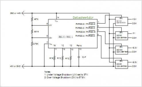
The PS10 saves board space, improves accuracy, eliminates optocouplers or level shifts, and reduces overall component count by combining four programmable timers, input under-voltage (UV) and over-voltage (OV) supervisors, a programmable power-on reset (POR), and four 90V open drain...
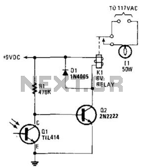
A phototransistor detects daylight. At dusk, it stops conducting, and Rl biases Q2, activating Kl, which turns on the light. At dawn, Ql begins to conduct, cutting off Q2. Kl deactivates, and the light turns off. The circuit utilizes a...
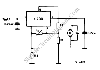
This diagram illustrates the usage of the L200 device for controlling the speed of permanent magnet motors. By utilizing resistors R1 and R2, the desired speed can be achieved. The L200 is a versatile integrated circuit designed for various applications,...
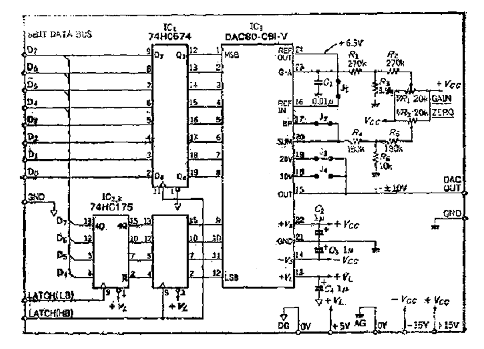
The 8 microcomputer data operates with an 8-bit parallel output, while also accommodating serial input for D-A converters. Typically, data must be entered in two groups and processed as a whole. The requirements for data latching involve 16 straight...
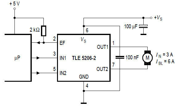
Stepper motor control circuit diagram using TLE5206 for remote control car. The stepper motor control circuit is designed to manage the operation of a stepper motor, specifically utilizing the TLE5206 integrated circuit. This circuit is particularly suitable for applications in...